Broken-end screw taking-out device

A technology for extractors and screws, applied in the field of extractors, can solve the problems of complex operation, waste of manpower and material resources, and high technical requirements for operation, and achieve the effect of convenient use and simple operation

Inactive Publication Date: 2004-06-16
上海神模电气有限公司
View PDF0 Cites 1 Cited by
  • Summary
  • Abstract
  • Description
  • Claims
  • Application Information

AI Technical Summary

Problems solved by technology

[0003] The technical problems to be solved by the present invention are: 1. The existing destructive method changes the size of the original threaded hole, which brings new problems to the installation; 2. A lot of waste of manpower and material resources; 3. The operation is complicated and difficult to operate. high technical requirements

Method used


Image

  • Broken-end screw taking-out device
  • Broken-end screw taking-out device

Examples


Embodiment Construction

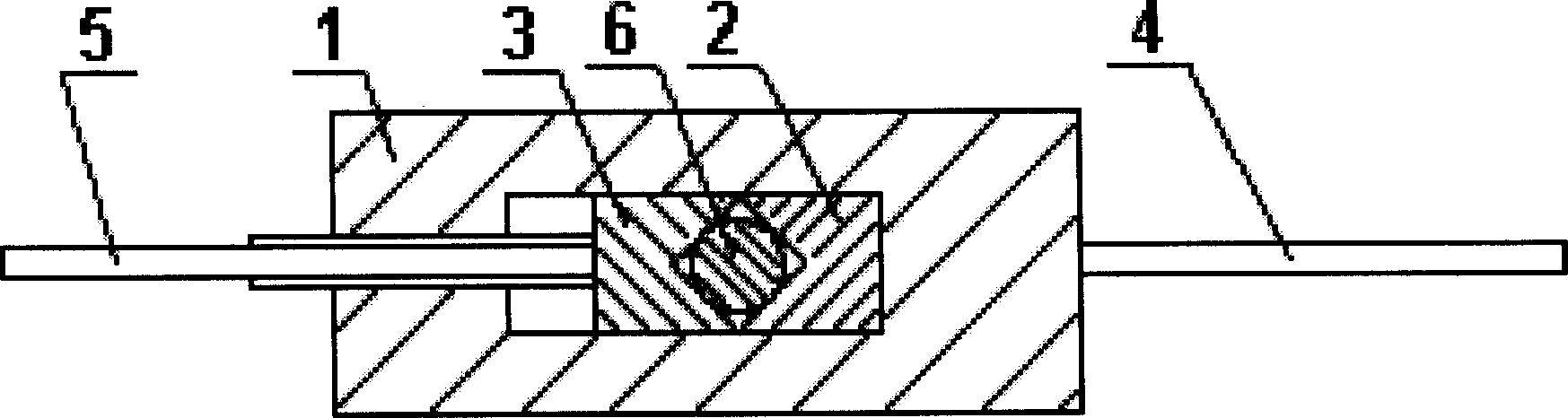
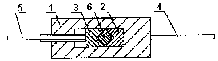
[0007] Such as figure 1 As shown, the screw extractor of the present invention is composed of a clamping frame 1, a fixed clamping die 2, a movable clamping die 3, a fixed rod 4, a movable rod 5 and a threaded rod 6. The middle part of the clamping frame 1 A rectangular hole is provided, the fixed clamping die 2 is arranged in the rectangular hole of the clamping frame 1, and the outer wall of the fixed clamping die 2 is connected to the outer wall of the rectangular hole of the clamping frame 1 , the specific connection method can be welded connection, the movable clamping die 3 is also arranged in the rectangular hole of the clamping frame 1, the outer wall of the movable clamping die 3 and the clamping frame 1 The outer walls of the rectangular holes are in contact with each other, and the fixed clamping die 2 and the movable clamping die 3 are provided with clamping openings, the clamping openings can be parallelograms, the fixed rod 4 and the The clamping frame 1 is fixe...


PUM


Abstract

The invention relates to an end breaking screw extractor which comprises a clamping rack, a retaining clamping mould, a movable clamping mould, a fixed bar, a movable bar and a screw-threaded bar. Compared with the prior art, the invention keeps the threaded hole dimension on one hand, and realizes easiness in use and simplicity of operation on the other hand.

Description

Technical field: [0001] The invention relates to a manual maintenance tool in the mechanical industry, in particular to an extractor used for extracting broken screws in threaded holes. Background technique: [0002] It is a frequent failure in the mechanical industry that the screw is broken and left in the threaded hole. In the existing technology, in order to take out the broken screw, a destructive method is usually used, such as using a drill to drill the broken screw into powder and then remove it. These destructive methods all have common shortcoming: 1, have changed the size of original threaded hole, bring new problem to installation; 2, waste manpower and material resources in a large amount; Invention content: [0003] The technical problems to be solved by the present invention are: 1. The existing destructive method changes the size of the original threaded hole, which brings new problems to the installation; 2. A lot of waste of manpower and material resource...

Claims


Application Information

Patent Timeline
Patent Type & Authority Applications(China)
IPC IPC(8): B25B27/02
Inventor 祝志斌
Owner 上海神模电气有限公司
Why Eureka
Try Eureka