Detecting apparatus for angle of rotation

A detection device, a technology of rotation angle, applied in the direction of measurement device, angle/taper measurement, electric device, etc., can solve the problem of not being able to correctly detect the rotation angle and so on

Inactive Publication Date: 2004-06-16
PANASONIC CORP
View PDF1 Cites 26 Cited by
  • Summary
  • Abstract
  • Description
  • Claims
  • Application Information

AI Technical Summary

Problems solved by technology

Therefore, when the detecting body 2 falls off from the rotating body 1 and the spur gear part 2A is damaged or worn out, the rotation angle cannot be detected accurately.

Method used


Image

  • Detecting apparatus for angle of rotation
  • Detecting apparatus for angle of rotation
  • Detecting apparatus for angle of rotation

Examples


Embodiment approach 2

[0040] A rotation angle detection device according to Embodiment 2 will be described. The same reference numerals are assigned to the same parts as those in the first embodiment, and detailed description thereof will be omitted.

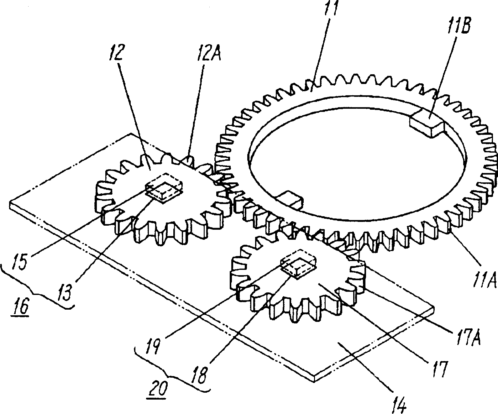
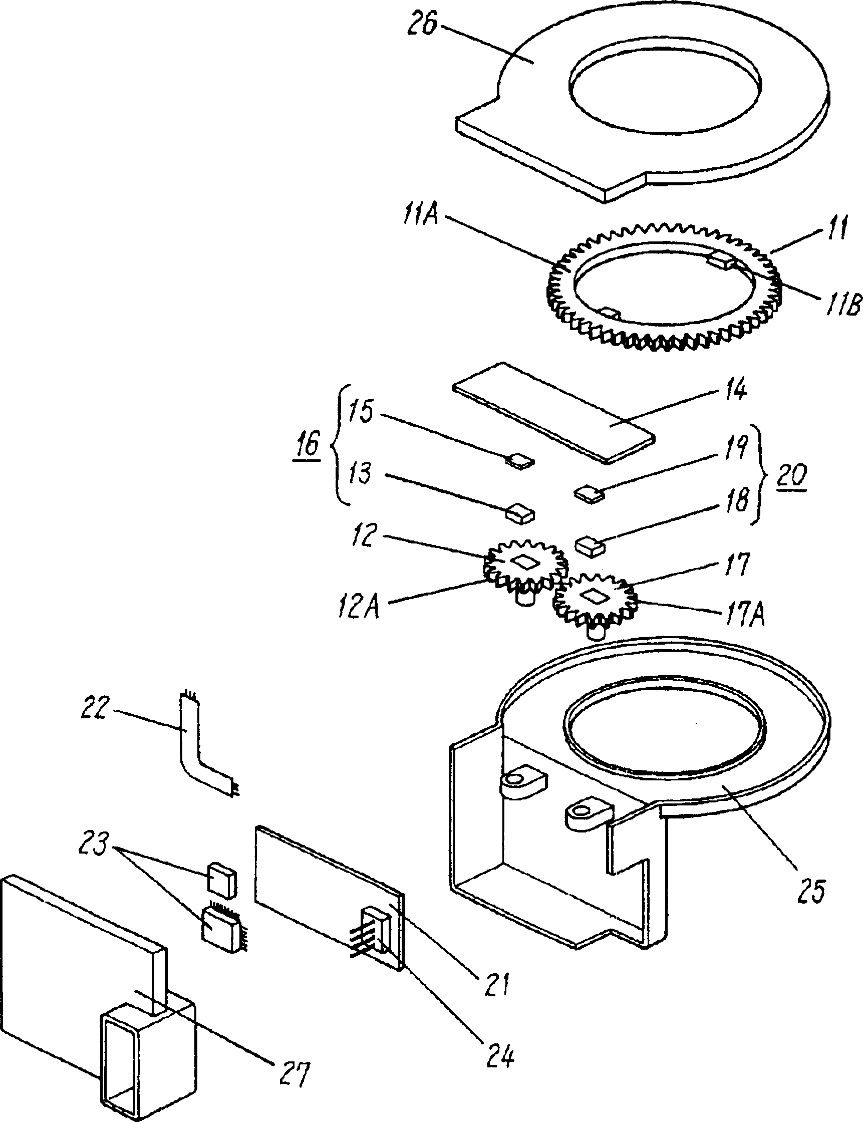
[0041] Figure 6 is a perspective view of a main part of the rotation angle detection device according to Embodiment 2 of the present invention. This detection device is the same as the first embodiment. The spur gear portion 12A on the outer periphery of the first detection body 12 and the spur gear portion 17A on the outer periphery of the second detection body 17 having the same number of teeth mesh with the spur gear portion 11A of the rotor 11 . The magnets 13 and 18 are attached to the centers of the first and second detection bodies 12 and 17 by insert molding. Magnetic detection elements 15 and 19 are respectively mounted on surfaces of wiring board 14A arranged substantially parallel thereon and facing detection bodies 12 and 17 , thereby ...


PUM


Abstract

A rotation angle detector includes a rotor, first and second detecting elements which rotate according to a rotation of the rotor, first and second detecting units for detecting rotations of the first and second detecting elements, respectively, and a control unit for detecting a rotation angle of the rotor based on a first signal when a difference between the first and second signals output from the first and second detecting units ranges within a predetermined range. The rotation angle detector has a simple structure and detects the rotation angle of the rotor accurately.

Description

technical field [0001] The present invention relates to a detection device for detecting the rotation angle of a rotating body such as a steering wheel of an automobile. Background technique [0002] In recent years, in the process of increasing the performance of automobiles, various detection devices are used to detect the rotation angle of the steering wheel for various controls. [0003] Figure 11 It is a perspective view of main parts of a conventional rotation angle detection device. A connecting portion 1B is provided, and is connected to a shaft of a steering wheel (not shown) inserted through the center portion of the rotating body 1 having the spur gear portion 1A formed on the outer periphery thereof. The spur gear portion 2A on the outer periphery of the detection body 2 meshes with the spur gear portion 1A of the rotor 1, and the magnet 3 is attached to the center of the detection body 2 by insert molding. The wiring board 4 is provided on the sample 2 almost...

Claims


Application Information

Patent Timeline
Patent Type & Authority Applications(China)
IPC IPC(8): G01B7/30B62D1/16B62D15/02G01B7/00G01D5/04G01D5/14G01D5/245
CPCB62D15/0215G01D5/04G01D2205/28
Inventor 大西贤英野村敏裕立石一郎西川寿中出义幸
Owner PANASONIC CORP
Why Eureka
Try Eureka