Rotary switch

A technology of rotary switch and turntable, which is applied in the direction of electric switch, capacitance measurement, electrical components, etc. It can solve the problems of inability to detect the rotation direction and amount of rotation of the turntable, the inability to detect the change of the magnetic field, and the inability to maintain the level.

Inactive Publication Date: 2014-04-23
HOSIDEN CORP
View PDF10 Cites 0 Cited by
  • Summary
  • Abstract
  • Description
  • Claims
  • Application Information

AI Technical Summary

Problems solved by technology

[0004] Due to the influence of the vibration of the turntable, etc., the ring magnet that generates the rotation signal may not be able to maintain the level with respect to the Hall IC that detects the change of the magnetic field (in addition, the flexible substrate, etc.)
At this time, the magnetic field detection element cannot detect the correct change in the magnetic field, and as a result, there is a problem that the rotation direction and the rotation amount of the turntable cannot be detected.

Method used


Image

  • Rotary switch
  • Rotary switch
  • Rotary switch

Examples


Embodiment Construction

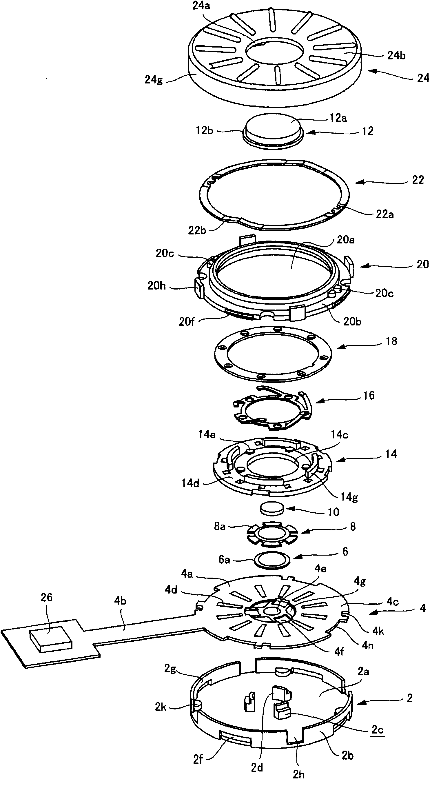
[0024] Hereinafter, the rotary switch 100 will be described as a specific example of the present invention. In addition, the technical idea of ​​the present invention is not limited to the specific structure shown as the rotary switch 100 . exist figure 1 , represents the appearance of the rotary switch 100 seen from directly above, in figure 2 represents the appearance of the rotary switch 100 seen from the front side, in image 3 means to use figure 1 A cross-sectional view of the rotary switch 100 is taken along line A-A'. exist Figure 4 shows an exploded perspective view of the rotary switch 100 seen from above in Figure 5 The middle is an exploded perspective view of the rotary switch 100 seen from below.

[0025] Such as Figure 4 As shown, the body 2 is thin-plate-shaped and constitutes a substantially circular shape. The body 2 has a fixed surface 2a and a peripheral wall 2b along the periphery. In addition, a plurality of body protrusions 2c are formed in ...


PUM


Abstract

The change in capacitance in association with the rotation of a dial is accurately sensed even when the dial is unstable. A rotary switch includes a body having a fixing surface, a thin-plate-like flexible substrate fixed onto the fixing surface and having a plurality of first electrodes arranged along a first circle on a first electrode placement surface, a thin-plate-like electrode plate having a plurality of second electrodes arranged along a second circle on a second electrode placement surface facing the first electrode placement surface, the electrode plate being rotatable along the second circle, a dial having an operating surface and rotatable along the second circle, and a resilient member interposed between an opposite operating surface of the dial and a resilient member surface. The electrode plate has a plurality of electrode plate protrusions in the circumferential direction on the resilient member surface. The dial has a plurality of dial protrusions in the circumferential direction on the opposite operating surface. Each of the electrode plate protrusions is positioned between the corresponding pair of the dial protrusions or each of the dial protrusions is positioned between the corresponding pair of the electrode plate protrusions.

Description

technical field [0001] The invention relates to a rotary switch for detecting the rotation direction and rotation angle of a turntable. Background technique [0002] A conventional rotary switch mainly includes a base, a magnetic field detection element (IC) disposed on the base, a rotatable dial, and a ring magnet that can rotate integrally with the dial. When the turntable rotates, the ring magnet also rotates integrally, and the magnetic field detection element detects a change in the magnetic field accompanying the rotation of the ring magnet to detect a rotation direction and a rotation amount. Details are described in Patent Document 1. [0003] Patent Document 1: Japanese Patent Laid-Open No. 2006-73311 [0004] Due to the influence of the vibration of the turntable, etc., the ring magnet that generates the rotation signal may not be able to maintain a level with respect to the Hall IC (or flexible substrate, etc.) that detects changes in the magnetic field. In thi...

Claims


Application Information

Patent Timeline
Patent Type & Authority Patents(China)
IPC IPC(8): H01H19/58H01H19/00H01H25/00H01H89/00
CPCH01H2025/048H01H25/065H01H2239/006G01R27/2605
Inventor 续木史郎
Owner HOSIDEN CORP
Why Eureka
Try Eureka