pump device

A pump device and pump chamber technology, applied in pump devices, electromechanical devices, pumps, etc., can solve the problems of low magnetic flux density and inability to detect the rotation angle of the rotor.

Active Publication Date: 2019-03-12
NIDEC SANKYO (ZHEJIANG) CORPORATION +1
View PDF7 Cites 0 Cited by
  • Summary
  • Abstract
  • Description
  • Claims
  • Application Information

AI Technical Summary

Problems solved by technology

[0006] However, in the pump device described in Patent Document 1, in the radial direction of the rotor, the outer peripheral surface of the driving magnet faces the end surface of the salient pole of the stator core, so that on the outer side of the driving magnet in the axial direction of the rotor, Low magnetic flux density generated by drive magnets
Therefore, if the magnetically sensitive surface of the Hall element faces the end face of the drive magnet in the axial direction of the rotor through the plate-shaped partition wall, there is a risk that the rotation angle of the rotor cannot be detected properly by the Hall element.

Method used


Image

  • pump device
  • pump device
  • pump device

Examples


Embodiment Construction

[0054] Below, while referring to the attached Figure 1 Embodiments of the present invention will be described.

[0055] (The overall structure of the pump unit)

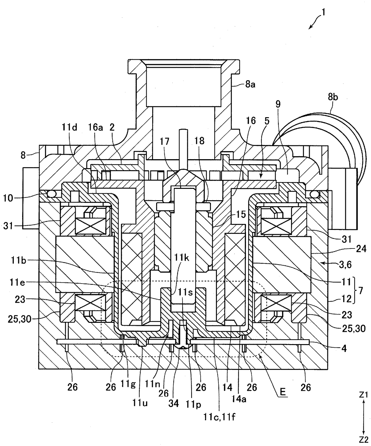
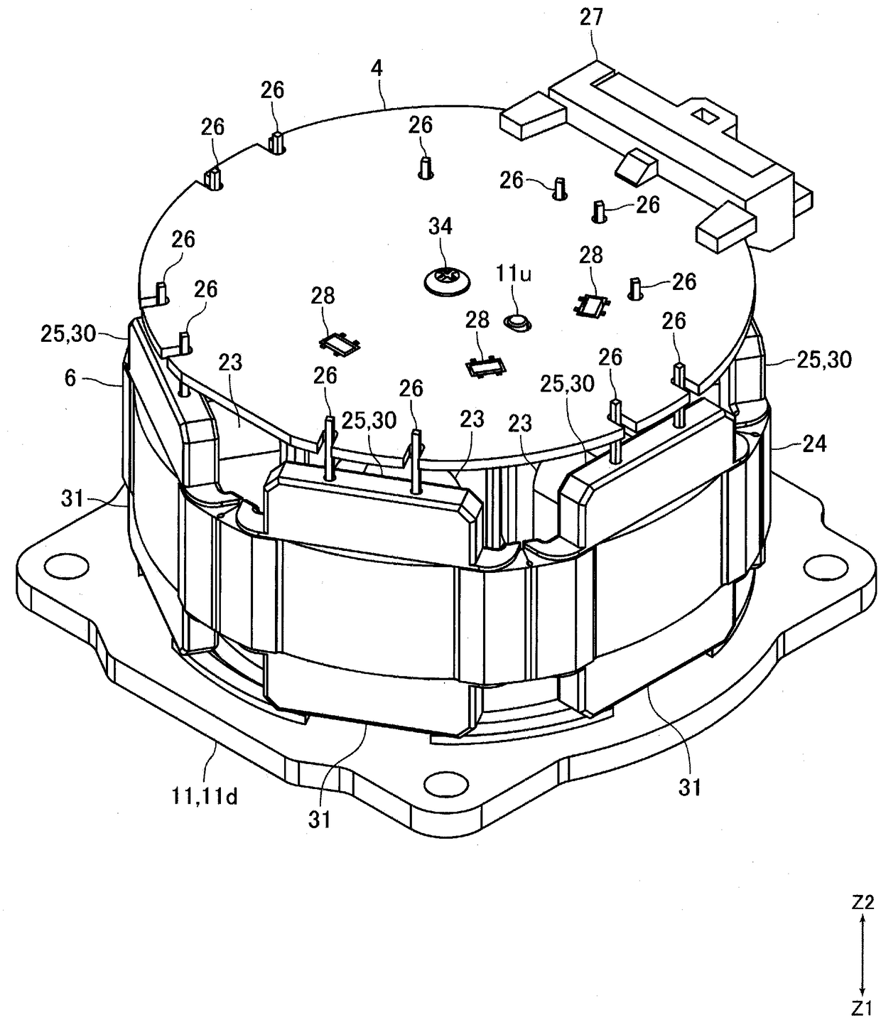
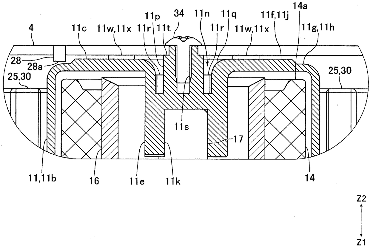
[0056] figure 1 It is a cross-sectional view of the pump device 1 according to the embodiment of the present invention. figure 2 yes figure 1 The perspective view of the circuit board 4, the stator 6, and the partition member 11 shown. image 3 is shown from the other direction figure 1 An enlarged cross-sectional view of part E. Also, in the following description, the figure 1 The upper side (Z1 direction side) as the "upper" side, the figure 1 The lower side (Z2 direction side) as the "lower" side.

[0057] The pump device 1 of the present embodiment is a type of pump called a sealed pump (sealed motor pump), and has: an impeller 2 ; a motor 3 for rotating the impeller 2 ; and a circuit board 4 for controlling the motor 3 . The motor 3 is composed of a rotor 5 and a stator 6 . The impeller 2 , the motor...


PUM


Abstract

Provided is a pump device capable of appropriately detecting the rotation angle of a rotor by using a detection element, even if a detection surface of the detection element mounted to a circuit board is facing a drive magnet via a base section of a partitioning member, in the axial direction of a rotor. In this pump device: the circuit board is fixed to the base section of the partitioning member by a fixing screw and is arranged further on a Z2 direction side than the base section; and the detection element is mounted to the circuit board such that the detection surface of the detection element faces the end surface of the drive magnet on the Z2 direction side, via the base section. In the base section, a recessed section is formed that is recessed toward the Z1 direction side from a surface of the base section on the Z2 direction side and a substrate fixing section is formed in the middle of the recessed section, said substrate fixing section having a female screw section to which the fixing screw engages formed therein. An end of the female screw section in the Z1 direction is arranged further on a first direction side than the surface of the base section on the Z2 direction side.

Description

technical field [0001] The present invention relates to a pump device including a rotor arranged in a pump chamber and a stator arranged outside the pump chamber. Background technique [0002] Conventionally, there is known a pump device including: a pump chamber in which an impeller and a rotor are arranged; and a stator and a circuit board arranged outside the pump chamber (for example, refer to Patent Document 1). In the pump device described in Patent Document 1, a partition wall is disposed between the pump chamber, the stator, and the circuit board to prevent fluid from flowing into the position where the stator and the circuit board are disposed. The partition wall has: an annular wall portion formed in a cylindrical shape and arranged between the rotor and the stator; and a disc-shaped plate-shaped wall portion closing the lower end of the annular wall portion. The rotor has a cylindrical driving magnet. The stator has a stator core having a plurality of salient po...

Claims


Application Information

Patent Timeline
Patent Type & Authority Patents(China)
IPC IPC(8): F04D13/06
CPCF04D13/0606F04D13/06H02K7/14H02K11/215H02K11/30
Inventor 大坪京史
Owner NIDEC SANKYO (ZHEJIANG) CORPORATION
Why Eureka
Try Eureka