Ligh conducting plate

A technology of light guide plate and light beam, applied in the field of light guide plate, can solve the problem of low light output brightness of the light guide plate, and achieve the effects of improving beam utilization rate, high light output brightness and simple structure

Inactive Publication Date: 2004-06-23
HONG FU JIN PRECISION IND (SHENZHEN) CO LTD +1
View PDF1 Cites 6 Cited by
  • Summary
  • Abstract
  • Description
  • Claims
  • Application Information

AI Technical Summary

Problems solved by technology

[0006] In order to overcome the problem of low light output brightness of existing light guide plates, the present invention provides a light guide plate with high light output brightness and excellent optical performance

Method used


Image

  • Ligh conducting plate
  • Ligh conducting plate
  • Ligh conducting plate

Examples


Embodiment Construction

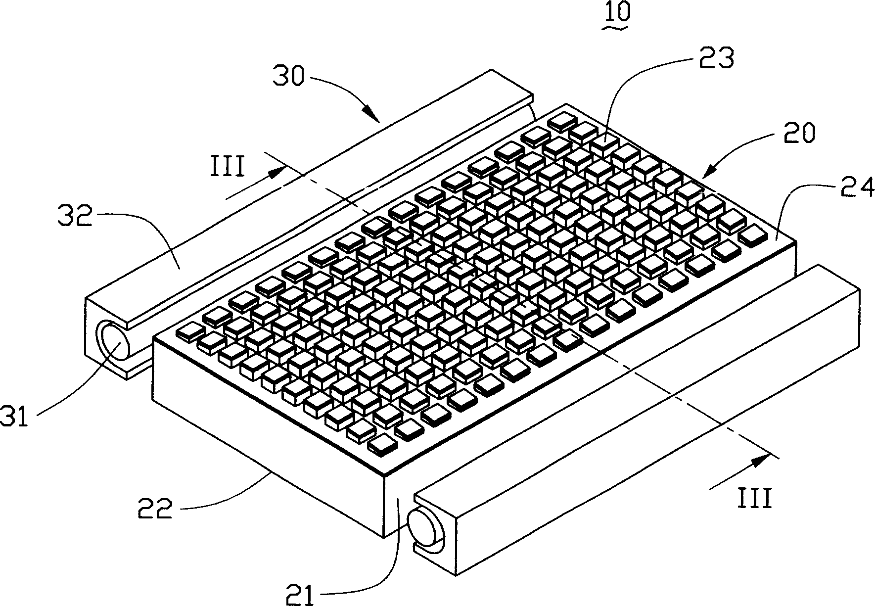
[0020] see figure 2 , is a light source system using the first embodiment of the light guide plate of the present invention, the light source system 10 includes a light guide plate 20 and two light sources 30 . The light guide plate 20 includes two incident surfaces 21 , an outgoing surface 22 connected to the incident surfaces 21 , and a bottom surface 24 opposite to the outgoing surface 22 . The light source 30 includes a lamp tube 31 and a reflector 32 partially surrounding the lamp tube 31 . The two light sources 30 are respectively disposed opposite to the two incident surfaces 21 of the light guide plate 20 .

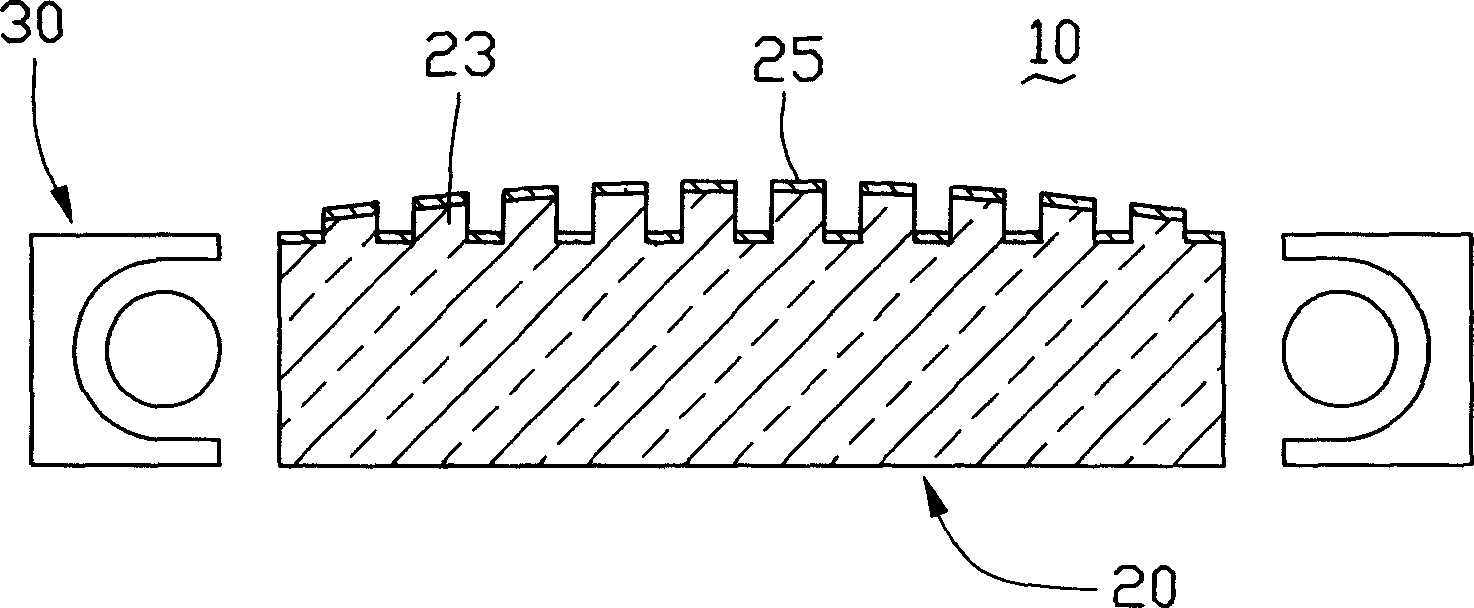
[0021] Please refer to figure 2 and image 3 , a plurality of protrusions 23 are distributed on the bottom surface 24 of the light guide plate 20 . The plurality of protrusions 23 are used to scatter light beams, break the total reflection condition of the light beams entering from the incident surface 21 and transmit inside the light guide plate 20 , and im...


PUM

PropertyMeasurementUnit
reflectanceaaaaaaaaaa

Abstract

The light conducting plate is used in guiding the transmission direction of light from light source to raise the brightness and homogeneity of emergent light. The light conducting plate includes incident plane for accepting light beam, emergent plane for guiding light beam and bottom plane opposite to the emergent plane, and the incident plane and the emergent plane intersect. The bottom plane has several distributed lugs to constitute curved surface in special shape and the curved surface can converge the light beams the lugs scatter to raise the emergent light brightness of the light conducting plate.

Description

【Technical field】 [0001] The invention relates to a light guide plate, in particular to a light guide plate with high luminance. 【Background technique】 [0002] Due to the advantages of lightness, thinness, and low power consumption, liquid crystal display devices are widely used in modern information equipment such as notebook computers, mobile phones, and personal digital assistants. Because the liquid crystal itself does not have light-emitting properties, it is necessary to provide a light source system for it to realize the display function. [0003] The existing light source system includes a light source and a light guide plate. The light source is arranged relative to the light incident surface of the light guide plate. The light guide plate guides the transmission direction of the light beam emitted from the light source, and converts the line light source or point light source into a surface light source to emit. A plurality of dots are distributed on the bottom s...

Claims


Application Information

Patent Timeline
Patent Type & Authority Applications(China)
IPC IPC(8): G02B5/02G02F1/13357G09F9/35
Inventor 吕昌岳陈杰良余泰成
Owner HONG FU JIN PRECISION IND (SHENZHEN) CO LTD
Why Eureka
Try Eureka