Method for calibarting lens anamorphic parameter

A calibration method and lens distortion technology, applied in the field of measurement, can solve the problems of many parameters, complex distortion models, and complex calibration process, and achieve the effect of less known conditions, good calibration effect, and high calibration accuracy

Inactive Publication Date: 2004-06-30
HUANGSHI BANGKE TECH CO LTD
View PDF0 Cites 35 Cited by
  • Summary
  • Abstract
  • Description
  • Claims
  • Application Information

AI Technical Summary

Problems solved by technology

The existing distortion parameter calibration methods have the following deficiencies: either the distortion model is complex, there are many parameters, and the amount of calculation is large; or although there are

Method used


Image

  • Method for calibarting lens anamorphic parameter
  • Method for calibarting lens anamorphic parameter
  • Method for calibarting lens anamorphic parameter

Examples


Embodiment

[0068] In order to verify the effect of the present invention, a simulation experiment and a real image experiment are carried out.

[0069] Digital simulation experiments.

[0070] In the simulation experiment, it is first assumed that the distortion parameter can be k1=k2=3.000e-4. Take four points on any straight line in the space, calculate its perspective imaging and distorted image coordinates, use the method of the present invention, use these image coordinates to calculate distortion parameters, and obtain

[0071] k1=0.000300000000002199, k2=0.000299999999995047 The error between the calibration value and the assumed value is only 7.330×10 -10 % and 1.650×10 9 %. It can be seen that the calibration accuracy of this method is very high.

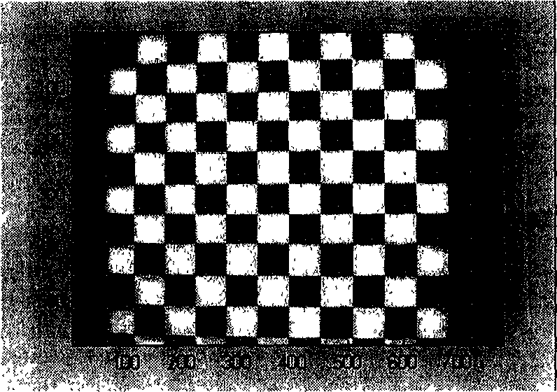
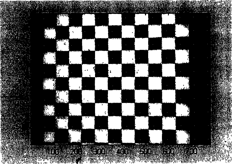
[0072] real image experiment

[0073] A total of three real image calibration experiments were done using three different lenses. The experimental results are as follows:

[0074] ① Use a lens with a focal length of 12mm, and th...


PUM


Abstract

The invention refers to the improvement of scaling method for lens deformation parameter. The steps are: places target, shoots target image, gets the coordinate of characteristic spot, and calculates the double ratio value CR of characteristic spot, obtains the expression of Xia, Xib, Xic, Xid, Yia, Yib, Yic, Yid, calculates the deformation parameter k1,k2.

Description

technical field [0001] The invention belongs to the technical field of measurement and relates to the improvement of a lens distortion parameter calibration method. Background technique [0002] In the visual inspection technology and endoscopic technology in the fields of industry and medical treatment, imaging equipment is used to obtain image information of the detected object. The imaging lens often has different degrees of distortion characteristics, which makes the obtained image relatively The real perspective projection image has certain distortion. Imaging lenses for industrial testing generally have small distortions that are difficult to detect with the naked eye. However, for measurement tasks that require high precision, it is still necessary to detect such weak distortion parameters and correct them. In some tasks of medical diagnosis and industrial maintenance, in order to obtain as much information as possible, the endoscope used often uses a lens with a lar...

Claims


Application Information

Patent Timeline
IPC IPC(8): G01M11/02
Inventor 张广军贺俊吉杨宪铭
Owner HUANGSHI BANGKE TECH CO LTD
Why Eureka
Try Eureka