

Concentrator for sound telephone set and local network communication method
A line-collecting device and communication method technology, applied in the direction of telephone communication, electrical components, automatic switching office, etc., can solve problems such as unification difficulties
- Summary
- Abstract
- Description
- Claims
- Application Information
AI Technical Summary
Problems solved by technology
Method used
Image

Examples
no. 2 Embodiment
[0075] Figure 5 It is a sequence diagram of the LAN communication method as the second embodiment of the present invention.
[0076] In the first embodiment, there is a problem that the voice telephone 8 cannot be called when the power of the PC 4 is turned off. That is, in the above-mentioned first embodiment, the call control related to the communication between the voice telephones is carried out by the PCs 1 and 4, and if the power of the PC 4 of the calling party is turned off, the call cannot be carried out. The second embodiment of the present invention is a LAN communication method which improves the above problems.
[0077] Figure 5 in and represents the first embodiment of the Figure 4 The difference is only the part represented by (B2), and the other parts represented by (A), (B), and (C) are the same as those of the first embodiment. Only the part of (B2) will be described below. In addition, unless otherwise indicated, "information" referred to below refer...
no. 3 Embodiment
[0086] Figure 6 It is a block diagram showing the structure of a TLA as a third embodiment of the present invention.
[0087] In above 1st and 2nd embodiment, although voice telephone set can take the simple structure that does not need 10 numeral keys, but can not accommodate general analog subscriber telephone. In the third embodiment here, a general analog telephone can be accommodated in a LAN.
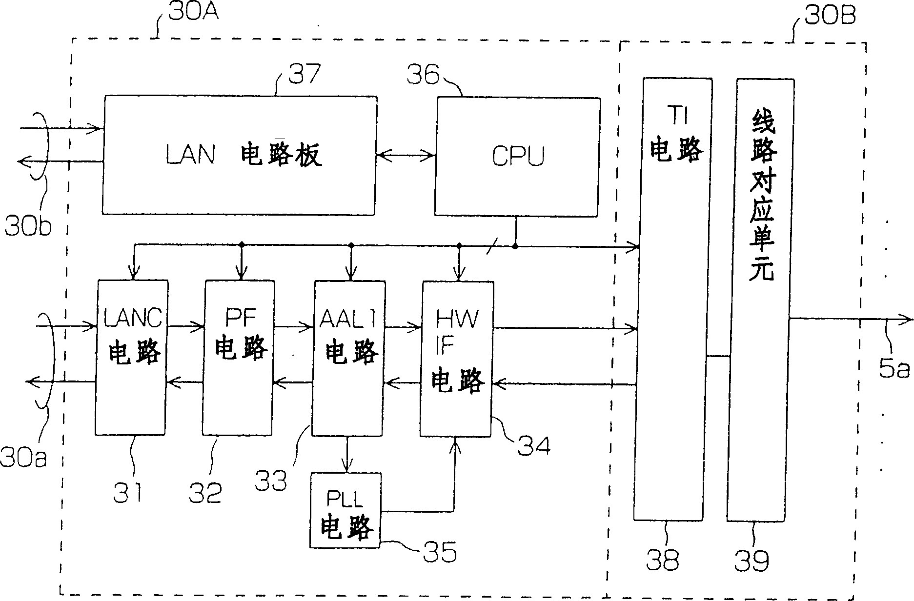
[0088] Here the TLA has the same figure 2 Same TLA control unit and with figure 2 Different interface components 60 .
[0089] The interface from the interface component 60 to the outside is a line interface of a general analog user, and terminals such as general analog telephones and G3 facsimile machines that are popular at present can be connected with this interface.
[0090] The interface module 60 has a so-called BORSCHT function necessary for an analog subscriber line in a switch, and performs operations such as power-on, ringing, dial pulse (PB / DP) monitoring, and t...
no. 4 Embodiment
[0093] compared to figure 2 or Figure 6 For the TLA 30, 40 shown in , in the TLA in the fourth embodiment, the function and These data packets are transmitted and received via the LAN-HUB interfaces 30B and 40B.
[0094]When such a function is provided, for example, the TLA control unit 30A in the TLA 30 can convert the voice data obtained from the interface unit 30B or 60 into UDP / IP (or TCP / IP) packets. Information related to call control is sent and received using the TCP / IP communication protocol. The UDP / IP (or TCP / IP) packet obtained in this process is sent to the LAN-HUB interface 30B. If there is a router connected to the LAN-HUB interface 30B, the data packet will be sent to the external network through the router.
[0095] In summary, in the above 4th embodiment, because the device that can carry out route selection through the IP address of router etc. is connected on the LAN-HUB interface, therefore can pass through IP network (such as Internet) and voice in ...
PUM
 Abstract
Description
Claims
Application Information