

Wave distribution board of speedboat yacht
A wave splitter and speedboat technology, applied in the direction of ships, hydrodynamic characteristics/hydrostatic characteristics, hulls, etc., can solve the problems of hindering the high-speed advancement of the hull, consuming the forward power of the hull, etc. Practical and convenient effects
Inactive Publication Date: 2004-08-11
傅德俐
View PDF0 Cites 4 Cited by
- Summary
- Abstract
- Description
- Claims
- Application Information
AI Technical Summary
Problems solved by technology
[0003] When the speedboat is running at high speed in the waves, the waves on both sides of the hull have little effect on the smooth running of the hull, but the forward bottom of the hull is basically a pot-bottom shape with an upward arc, and the waves hit the forward The bottom, which greatly hinders the high-speed advancement of the hull
Although water is a liquid and has no fixed shape and hardness, once the water is hit by high-speed impact, due to the lack of time to disperse, the resistance between the water and the water is generated, and it also produces a huge reverse thrust, so that the waves force The front of the hull jumps up while consuming the forward momentum of the hull
Method used
View moreImage
Smart ImageViewing Examples

Examples
Embodiment Construction
[0013] Below in conjunction with accompanying drawing, the present invention is described in further detail with preferred embodiment:
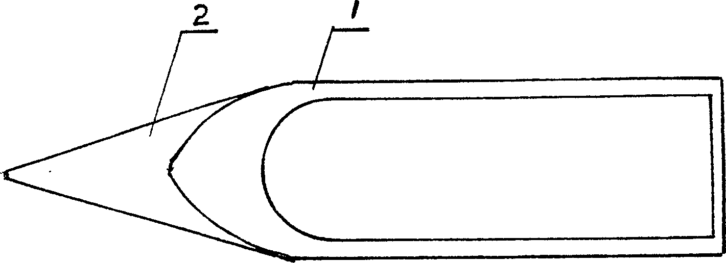
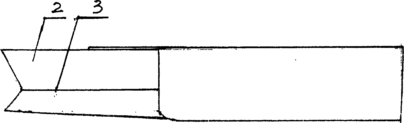
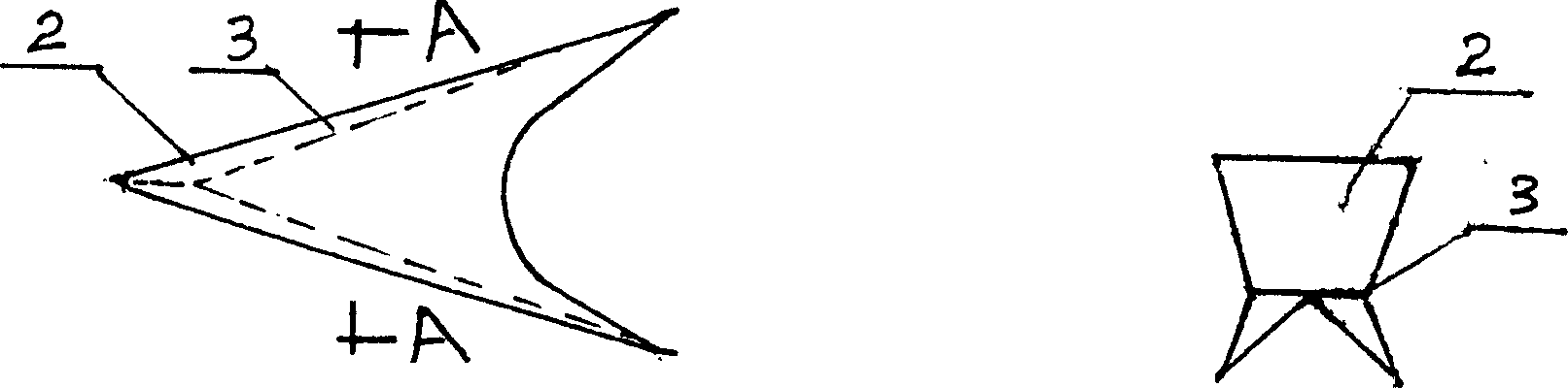
[0014] The present invention is a triangular integral wave splitter (2) fixedly arranged on the front part of the hull (1). 1) fixedly connected, triangular push plates (4) are provided on both sides of the water line (3) bottom of the wave splitter (2). When the hull is running fast in the water, the two side push plates (4) at the bottom of the waterline of the wave splitter (3) separate the waves from the middle in the water, and the waves on the side are slightly stirred up by the inclined plane and separated to the two sides. Reach the purpose that the hull is like running on calm water.
Login to View More PUM
 Abstract
A wave-dividing plate for motor boat has a triangular shape and features that its front part is composed of two plates linked together and its back part has a width same as that of hull bottom and is connected to the hull bottom. Under the floating line it has the triangular push plates at both sides. When a motor boat is running at high speed, the wave is divided by it to form a smooth water way on which the motor boat is running, resulting in high stability and no jump.
Description
(1) Technical field [0001] The invention relates to a speed boat wave splitter used for various small and medium speed boats on water. (2) Background technology [0002] From ancient times to the present, the forward bottom of all ships on the water is basically in the shape of a pot bottom in an arc upwards, which directly presses the waves. As a result, the waves directly collide with the hull forward to the bottom, causing the hull to bump and jump, and at the same time greatly consume the power of the hull. This phenomenon is more obvious when the hull travels faster. Anyone who has been on a speedboat has a headache from the bumping and beating of the hull, but they have no choice but to believe that this is an unavoidable theorem. [0003] When the speedboat is running at high speed in the waves, the waves on both sides of the hull have little effect on the smooth running of the hull, but the forward bottom of the hull is basically a pot-bottom s...
Claims
Login to View More Application Information
Patent Timeline
 IPC IPC(8): B63B1/32
CPCY02T70/12B63B1/06
Inventor傅德俐
Owner傅德俐