Electric power driven hydrostatic test block valve for thermal power generation

A hydrostatic test and valve blocking technology, which is applied to sliding valves, engine components, valve devices, etc., can solve the problems of labor-intensive pipeline blocking, high labor intensity, and expensive valve blocking

Active Publication Date: 2004-08-25
WENZHOU FEIQIU POWER STATION VALVE MFG CO LTD
View PDF0 Cites 8 Cited by
  • Summary
  • Abstract
  • Description
  • Claims
  • Application Information

AI Technical Summary

Problems solved by technology

[0003] In order to solve the problems of labor-intensive, time-consuming, labor-intensive and expensive blocking of the pipeline when the pipeline is subjected to a high-pressure water pressure test before being put into operation in the current thermal power plant, the technical solution of the present invention is: The lower part of the plug valve body has a horizontal pipe that can connect the pipes at both ends. The upper part of the valve body has a bonnet with a sealing device. The top of the valve body is equipped with an electric device. The cen...

Method used


Image

  • Electric power driven hydrostatic test block valve for thermal power generation
  • Electric power driven hydrostatic test block valve for thermal power generation
  • Electric power driven hydrostatic test block valve for thermal power generation

Examples


Embodiment Construction

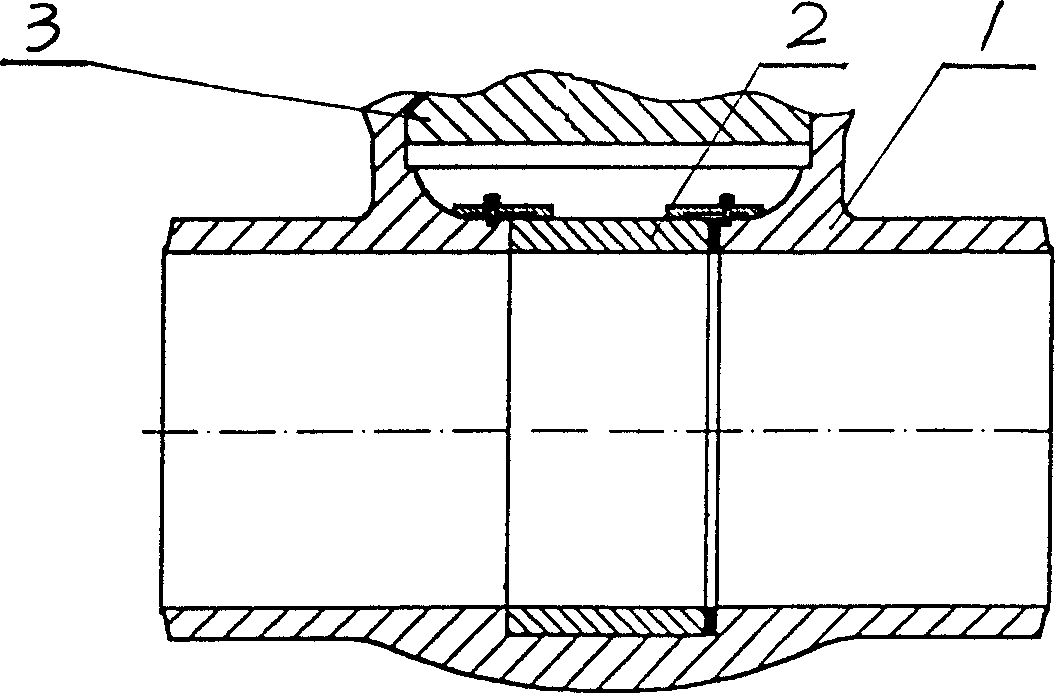
[0017] figure 1 When the pipeline in the prior art is in normal operation, a diversion sleeve 2 is fixedly installed in the pipe groove of the valve body 1, and a sealing member and a sealing cover 3 are installed at the opening of the upper part.

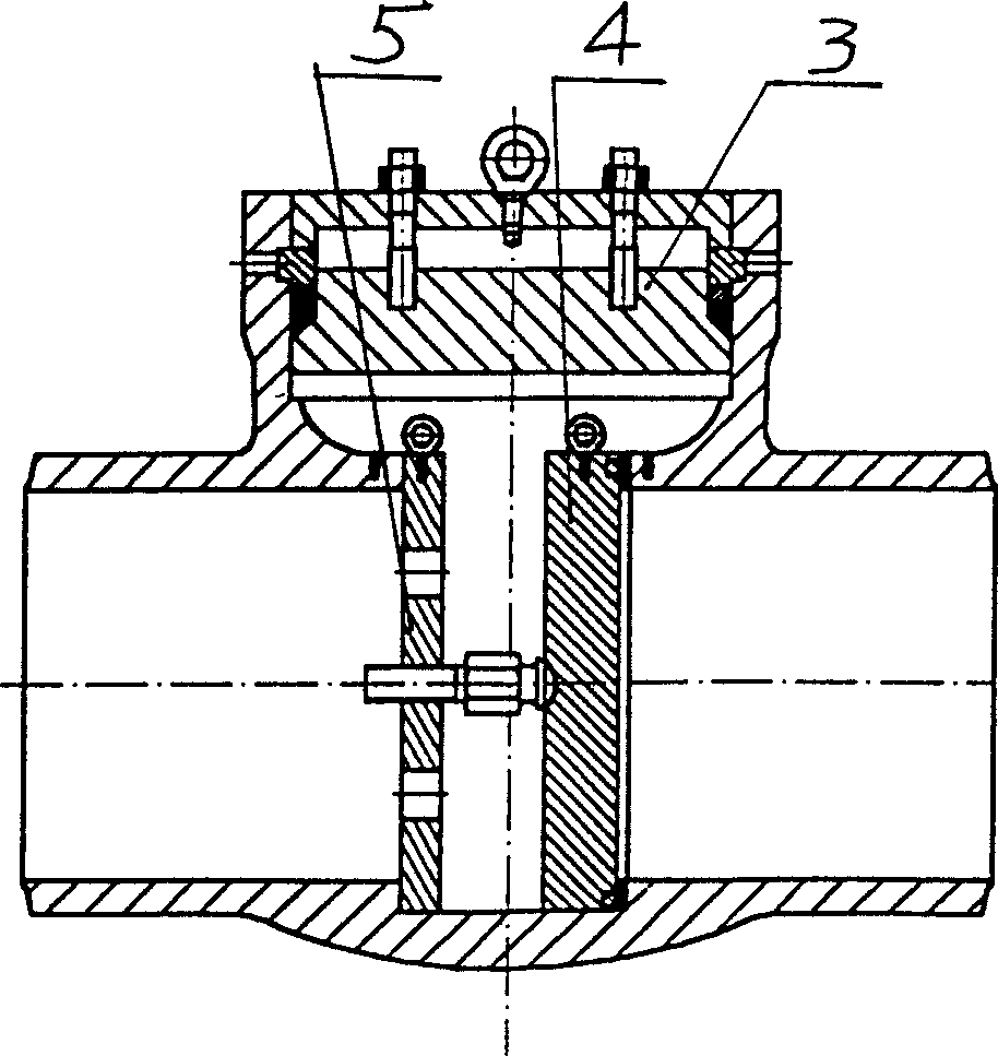
[0018] figure 2 It is the structural diagram of the pipeline in the prior art when the valve is blocked under the pressure test state. When the hydraulic test is required, the sealing cover 3 and the seal below it are opened, the diversion sleeve 2 is taken out, and the diversion sleeve 2 is installed. Install the blocking plate 4 and the support plate 5 on the two ends of the pipeline respectively, and then tighten the bolts so that the blocking plate 4 and the valve seat are pressed tightly, so that water can be passed through for the hydraulic test.

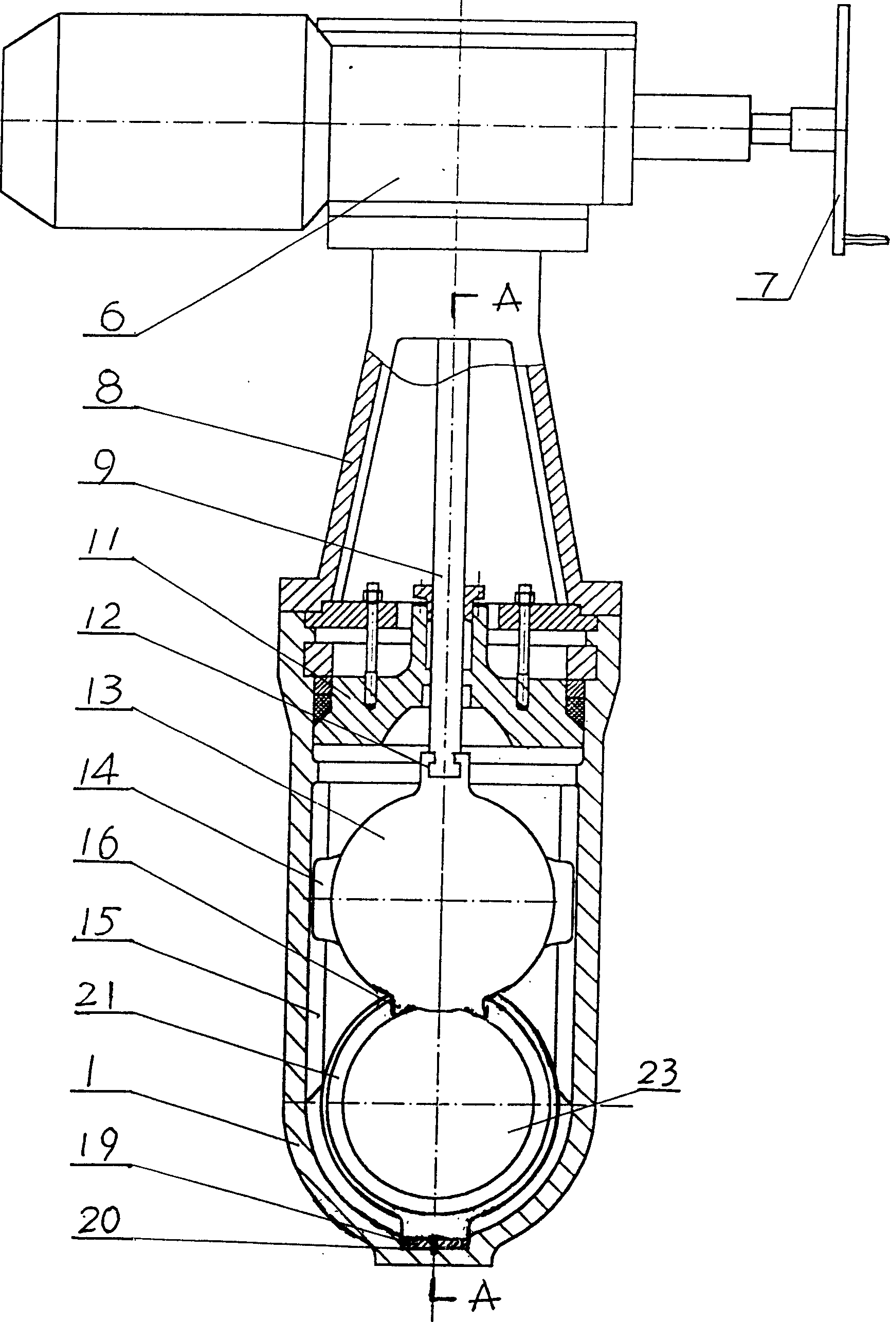
[0019] image 3 Among them, there is a horizontal pipe 23 (see Figure 4) that can connect the pipes at both ends at the lower part of the plugging valve body 1, and a bonnet 11 ...


PUM


Abstract

The present invention discloses an electric hydraulic test plugging valve for steam-electric power generation, and it is characterized by that the lower portion of valve body of plugging valve is equipped with a cross pipe which can be used for connecting pipeline, the upper portion of the valve body is equipped with valve cover, and on the top portion of said valve body an electric device is mounted, the upper end of the valve rod is connected with the electric device, and its lower portion is connected with valve flap mounted in the valve body, on the ring recessed groove positioned at side surface of valve flap and mounted in the interior of cross pipe a valve seat is set, said valve seat is formed from inner valve seat and outer valve seat which can be leftward and rightward floated, an elastic sealing body is mounted between inner and outer valve seat, and a spring is mounted beween outer valve seat and bottom wall of ring recessed groove on the valve body. Said plugging valve can quickly implement conversion of opening and closing functions.

Description

technical field [0001] The invention belongs to a valve, in particular to a plugging valve used in a hydraulic test for a pipeline for thermal power generation. Background technique [0002] The working temperature of pressure steam pipelines used in thermal power plants is generally above 540 degrees, and the working pressure is greater than 14MPa. To carry out the high-pressure water delivery test on the pipeline at normal temperature, one end of the pipeline should be blocked during the test, and the water under pressure should be input from the other end to make it reach the specified pressure value before it can be used without leakage. In the prior art, all adopt figure 1 , figure 2 The blocking valve of the structure shown above is installed on the pipeline, figure 1 For high temperature operation, a guide sleeve 2 is fixedly installed in the pipe groove of the valve body 1, and a seal and a sealing cover 3 are installed at the upper opening; figure 2 For the st...

Claims


Application Information

Patent Timeline
IPC IPC(8): F16K3/20
Inventor 钟立生杨志聪
Owner WENZHOU FEIQIU POWER STATION VALVE MFG CO LTD
Why Eureka
Try Eureka