Valve mechanism of pneumatic automobile engine

A pneumatic vehicle and gas distribution mechanism technology, applied in the direction of engine components, machines/engines, mechanical equipment, etc., can solve problems such as energy loss

Inactive Publication Date: 2004-09-01
ZHEJIANG UNIV
View PDF0 Cites 3 Cited by
  • Summary
  • Abstract
  • Description
  • Claims
  • Application Information

AI Technical Summary

Problems solved by technology

if p 2 Air intake, work according to the process A-B-C, then the gas pressure in the cylinder at

Method used


Image

  • Valve mechanism of pneumatic automobile engine
  • Valve mechanism of pneumatic automobile engine
  • Valve mechanism of pneumatic automobile engine

Examples


Embodiment Construction

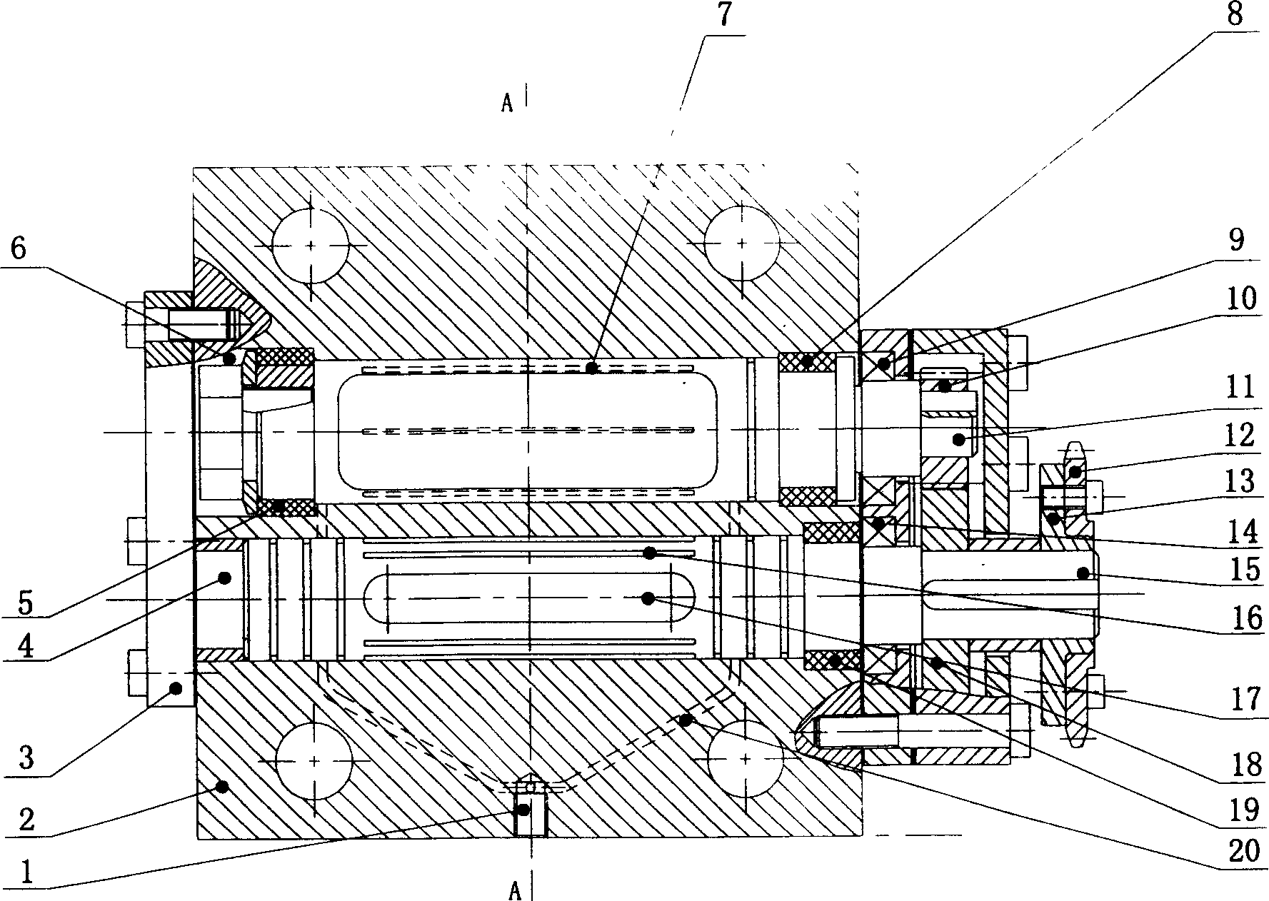
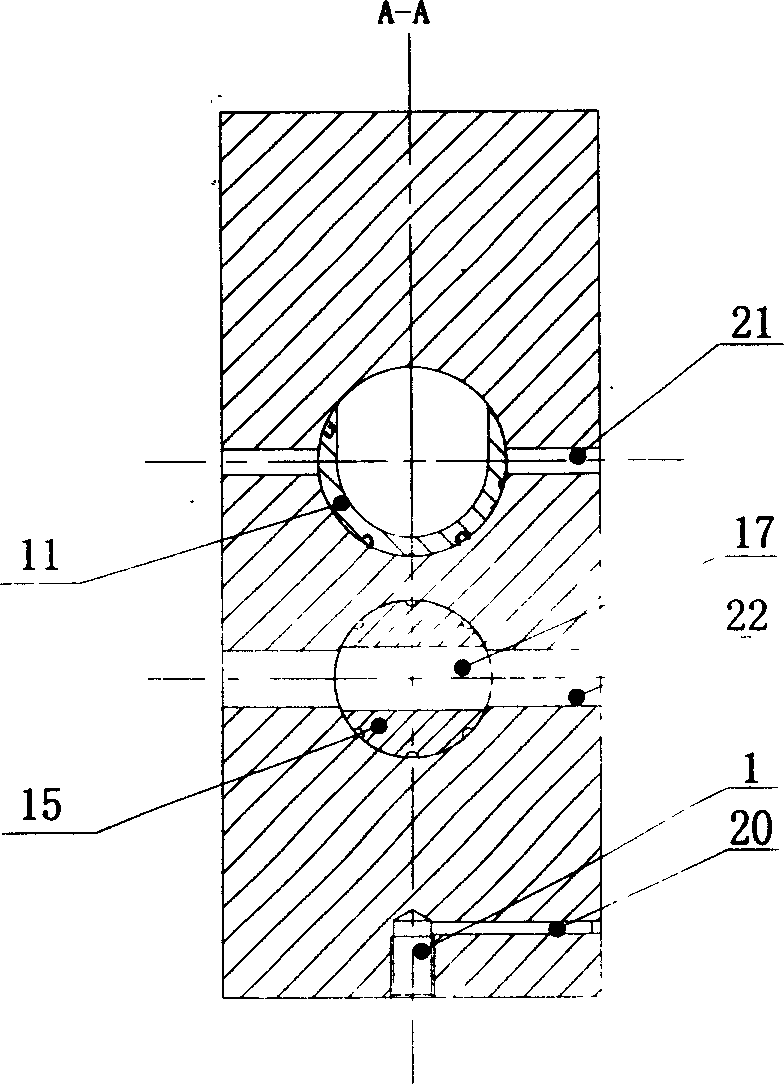
[0013] refer to figure 2 , image 3 , the gas distribution mechanism of the pneumatic automobile engine of the present invention comprises cylinder head 2, intake valve 11, exhaust valve 15, and cylinder head 2 has two cylindrical holes 4,6 parallel to each other spaced apart and two crossing cylindrical apertures respectively. The intake passage 21 and the exhaust passage 22, the intake valve 11 and the exhaust valve 15 are respectively placed in the two cylindrical holes 4, 6 of the cylinder head, and are rotationally matched with the cylindrical holes, and the two cylindrical holes One end is closed by an end cap 3 fixed to the cylinder head. The two ends of the intake valve 11 are respectively equipped with sealing rings 5 ​​and 8 for preventing the leakage of high-pressure gas in the cavity of the intake valve. The two sealing rings can adopt standard Y x type sealing ring. There is a section of valve body with a U-shaped cross section between the two sealing rings, w...


PUM


Abstract

The invention is an air-distributing mechanism of air-driven automobile engine, mainly including cylinder end, air inlet valve and exhaust valve, where the cylinder end has two parallel-separated columnar holes and air inlet channel and exhaust channel, the air inlet valve and the exhaust valve are set in the two columnar holes, respectively and rotationally cooperate with them, two ends of the air inlet valve are installed with seal washers, respectively, the valve body between the two seal washers has U-cross section to compose the cavity of the air inlet valve, there is an exhaust notch corresponding to the exhaust channel on the exhaust valve, and there is a gear engaging the two valves on one end where the two valves extend out of the columnar hole. It can ensure the maximum pressure occurs at the top stop point in the cylinder, effectively reduce throttling and flowing losses, and largely enhance the economic property of the automobile engine.

Description

technical field [0001] The invention relates to a gas distribution mechanism of a pneumatic automobile engine. Background technique [0002] The development of automobiles faces environmental protection and energy issues. Automobiles consume half of the world's oil production, automobile exhaust is the main cause of urban air pollution, and greenhouse gases emitted by automobiles account for the largest proportion of global human greenhouse gas emissions. In order to achieve sustainable development, the concept of a pneumatic vehicle powered by a pneumatic vehicle engine is proposed. Pneumatic vehicle engine is a kind of power machinery that converts the energy stored in the working fluid into mechanical energy output. The intake process is in a high-pressure state, and the intake method and work process directly affect the power performance and economic performance of the engine. [0003] The efficiency of the pneumatic vehicle engine is the pri...

Claims


Application Information

Patent Timeline
IPC IPC(8): F01L7/02
Inventor 蔡金雷元广杰沈瑜铭俞小莉
Owner ZHEJIANG UNIV
Why Eureka
Try Eureka