Constant current controller and power regulation circuit thereof

A technology for power regulation and circuit regulation, applied in control/regulation systems, regulation of electrical variables, energy-saving control technology, etc., can solve problems such as system false triggering of overheating protection, reliability reduction, and low efficiency, and achieve the goal of changing output power Effect

Active Publication Date: 2018-08-28
SHANGHAI BRIGHT POWER SEMICONDUCTOR CO LTD
View PDF8 Cites 3 Cited by
  • Summary
  • Abstract
  • Description
  • Claims
  • Application Information

AI Technical Summary

Problems solved by technology

This results in higher driver chip temperatures, lower efficiency and reduced reliability
In more serious cases, the system will accidentally trigger the overheating protection

Method used


Image

  • Constant current controller and power regulation circuit thereof
  • Constant current controller and power regulation circuit thereof
  • Constant current controller and power regulation circuit thereof

Examples


proportion K

[0068]

[0069] Example: if (W / L) MN3 =(W / L) MN4 =(W / L) MN5 , (W / L) MP2 =(W / L) MP3 , I NADJ =(1 / 2)*I P , then K=1 / 2.

[0070] That is, assuming that the second current I N1 with current I P1 equal, the first current I P2 is the current I P1 with FM current I NADJ The difference, and thus also the second current I N1 with FM current I NADJ Difference. Of course, as long as the first current I P2 and the second current I N1 One of the FM current I NADJ Correlation (positive correlation or negative correlation), that is, the frequency modulation current I NADJ It has the function of adjusting the reproduction ratio.

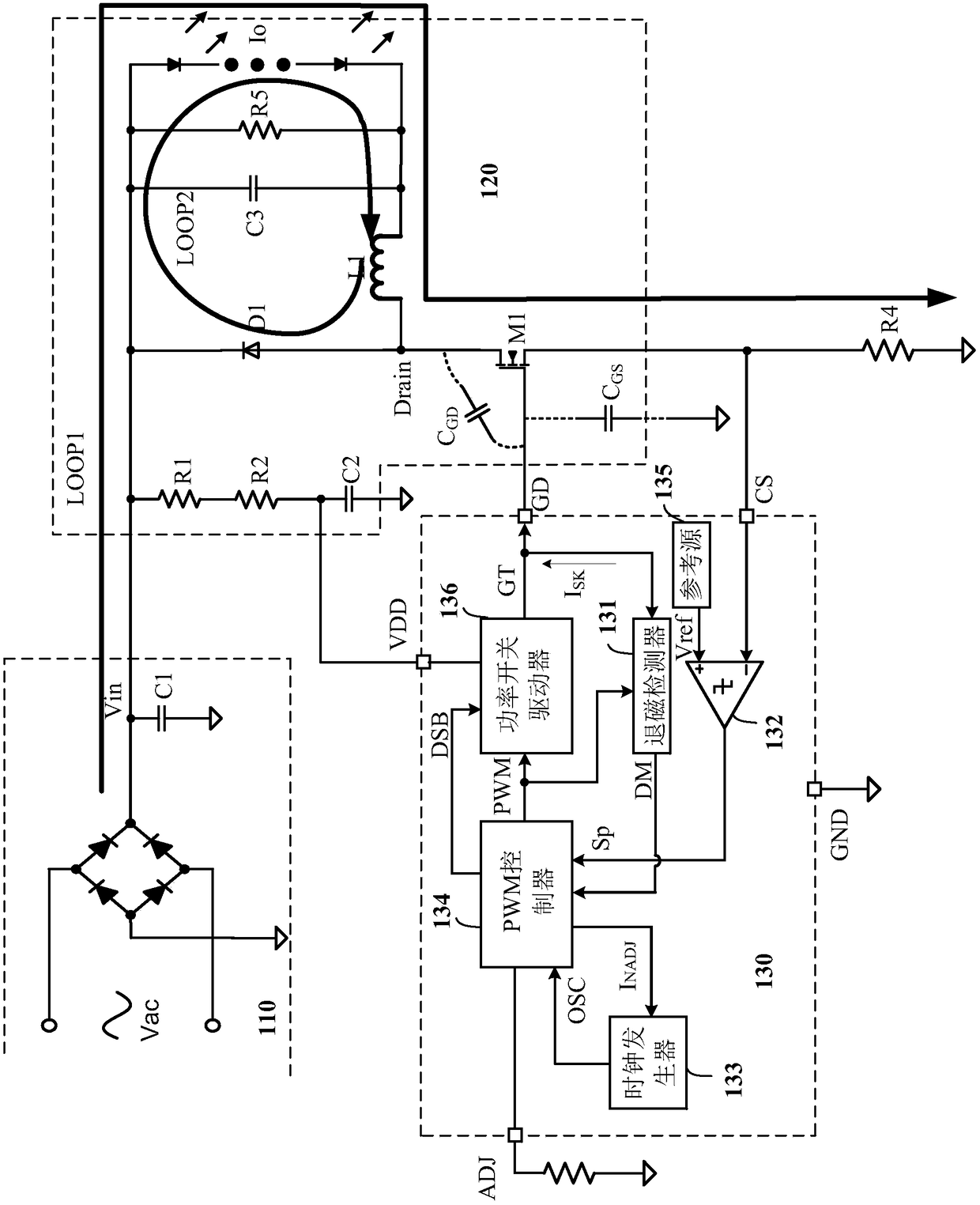
[0071] Figure 9 yes image 3 Schematic diagram of each signal waveform of the circuit shown. combined reference image 3 with Figure 9 As shown, CLK is the system clock signal, CLKPO is the system frequency divided by 4, the high level duty cycle is 25%, and the output current Iout is the LED current waveform. On the falling edge of CLK, ...


PUM


Abstract

The invention provides a power regulation circuit for a load. The power regulation circuit comprises a dynamic frequency adjustment circuit, an electrical level reproduction circuit, a reproduction ratio setting circuit, a sampling comparison circuit and a PWM generator. The dynamic frequency adjustment circuit receives a first clock signal and a variable frequency control signal to generate a second clock signal. The electrical level reproduction circuit generates an electrical level reproduction detection signal according to the second clock signal, wherein the high electrical level of the second clock signal is duplicated to the high electrical level of the electrical level reproduction detection signal. The reproduction ratio setting circuit sets the reproduction ratio of time of duration of reproduction from the high electrical level of the second clock signal to the high electrical level of the electrical level reproduction detection signal according to the frequency modulation current, wherein the reproduction ratio is smaller than 1:1. The sampling comparison circuit compares the electrical level reproduction detection signal and a current sustain signal to generate the variable frequency control signal and feeds back to the dynamic frequency adjustment circuit. The PWM generator generates a PWM signal based on the second clock signal.

Description

technical field [0001] The invention mainly relates to a driving circuit, in particular to a constant current controller and a power regulating circuit thereof. Background technique [0002] Light-emitting diode (LED) is a light source and display device made of third-generation semiconductor materials. It has the characteristics of low power consumption, long life, no pollution, rich colors, and strong controllability. It is a revolution in lighting sources and the light industry. With the development of LED, more and more LED lighting products are pouring into the market. The electronic drive part of LED is an indispensable part of LED lighting products. [0003] figure 1 It is a typical LED drive circuit. refer to figure 1 As shown, the LED driving circuit includes a bridge rectifier 101 and a power converter 102 . The input end of the bridge rectifier 101 is connected to the AC input voltage AC, and the output end is connected to the power converter 102 and the LED ...

Claims


Application Information

Patent Timeline
Patent Type & Authority Applications(China)
IPC IPC(8): G05F1/66H05B33/08H05B44/00
CPCG05F1/66H05B45/37Y02B20/40
Inventor 刘慧明卢鹏飞李振华朱臻
Owner SHANGHAI BRIGHT POWER SEMICONDUCTOR CO LTD
Why Eureka
Try Eureka