High frequency component and installation structure thereof

A component and high-frequency technology, applied in the field of high-frequency components and their installation structures, can solve the problems of inability to achieve thinning, inability to achieve lightweight, and cost increase

Inactive Publication Date: 2004-09-01
ALPS ALPINE CO LTD
View PDF1 Cites 1 Cited by
  • Summary
  • Abstract
  • Description
  • Claims
  • Application Information

AI Technical Summary

Problems solved by technology

[0010] Since the frame body 51 of the conventional high-frequency module is formed of a rectangular parallelepiped determined by the size of the front panel 52, it becomes a large-scale structure, and weight reduction cannot be achieved, and there is a problem that the cost of materials is large, which increases the cost.
[0011] Also, because the mounting feet 52a, 55a protrude downw

Method used


Image

  • High frequency component and installation structure thereof
  • High frequency component and installation structure thereof
  • High frequency component and installation structure thereof

Examples


Embodiment Construction

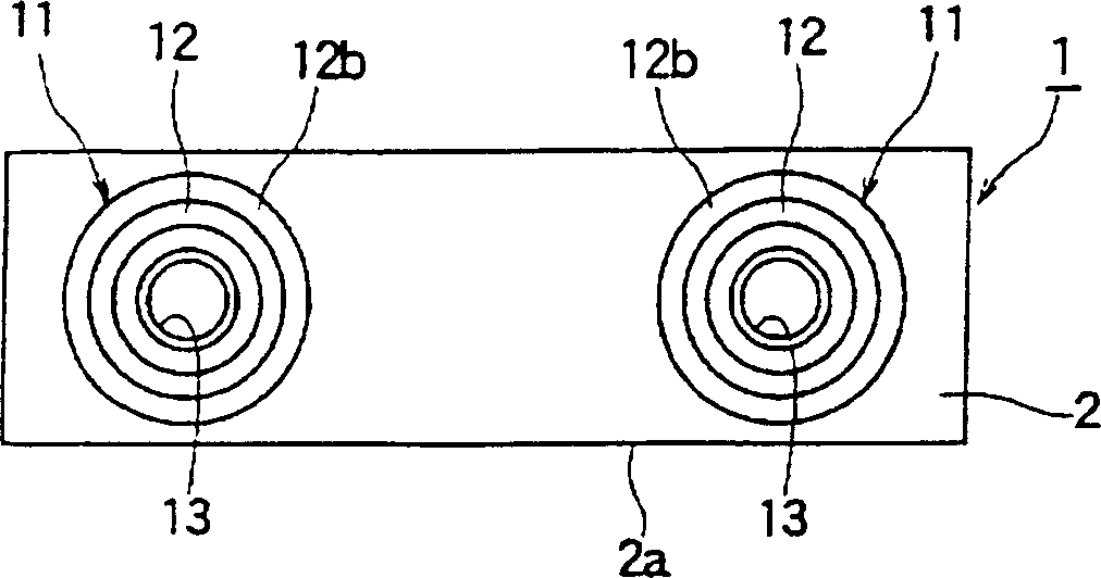
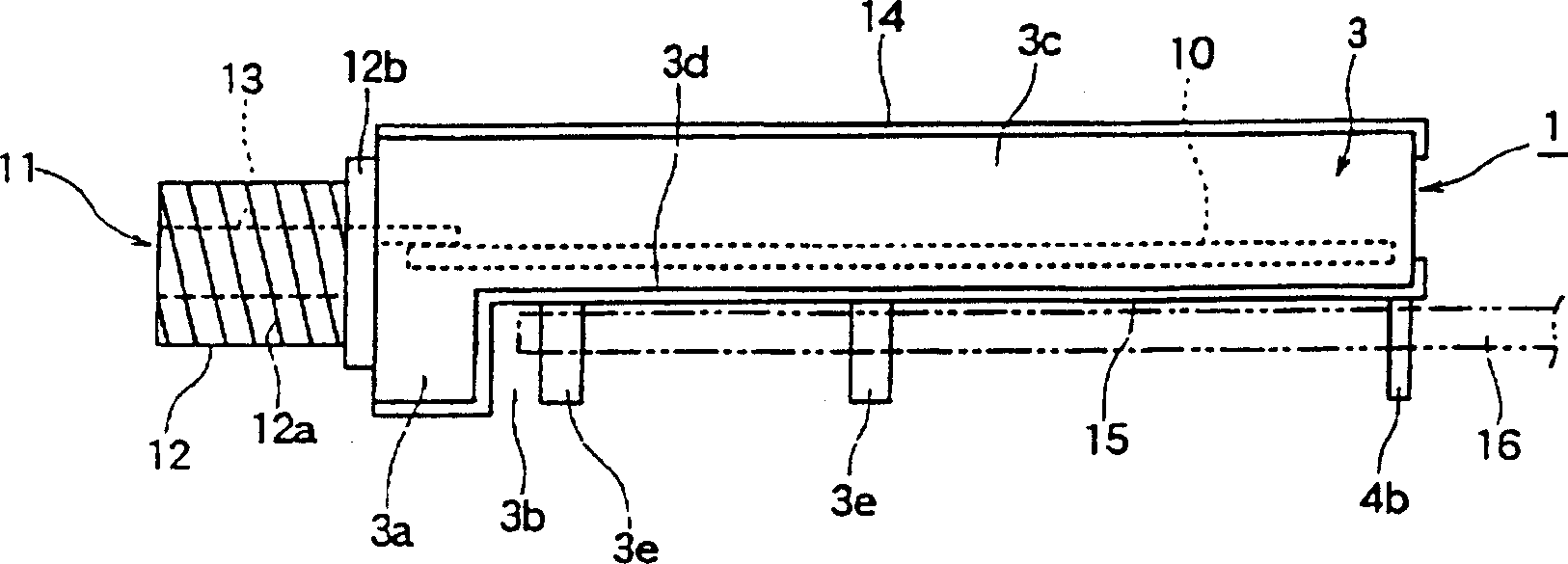
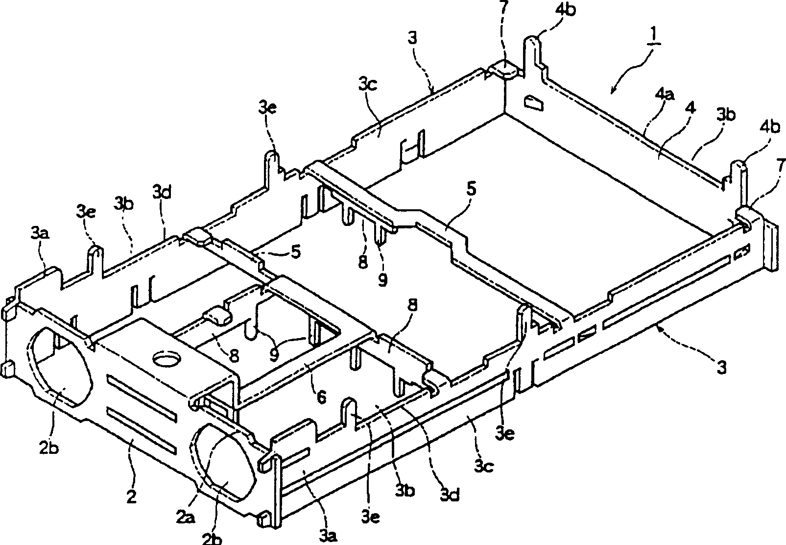
[0030] Below, a schematic diagram illustrating the high-frequency component of the present invention and its installation structure, figure 1 It is a front view showing the first embodiment of the high-frequency module of the present invention. figure 2 It is a side view showing the first embodiment of the high-frequency module of the present invention and its mounting structure. image 3 It is a perspective view showing a state in which the housing is turned upside down in the first embodiment of the high-frequency module of the present invention. Fig. 4 is an explanatory diagram showing a method of manufacturing a frame of the first embodiment of the high-frequency module of the present invention.

[0031] 5 is a perspective view showing a housing according to a second embodiment of the high-frequency module of the present invention. Figure 6 It is an explanatory drawing showing the manufacturing method of the housing according to the second embodiment of the high-freque...


PUM


Abstract

Provided is an inexpensive high-frequency unit which can be made small-sized, thin, and lightweight and is efectively using the material and its fitting structure. A frame body 1 has a rectangular front plate 2, a couple of side plates 3 which extend backward from the short side of the front plate 2, and a rear plate 4 which closes the rear side of the couple of side plates 3. The couple of side plates 3 each have a thin-width part 3c which is narrower than the width of the front plate 2 in the height direction and formed over the rear end while having a step 3b with the upper edge or lower edge of the front plate 2 and a fitting leg 3e which extends from one edge 3d of the thin width part 3c toward the step 3b, so the frame body 1 is a rectangular parallelepiped shape formed between a couple of thin parts 3c which are smaller than the front plate 2, and the frame body is made smaller than before and requires less materials to make it lightweight.

Description

technical field [0001] The present invention relates to a high-frequency component suitable for a TV tuner and the like and its mounting structure. Background technique [0002] Next, the structure of the previous high-frequency components will be described with reference to FIG. , and an upper panel 53 extending rearward; a lower panel 54 embedded with the short side below the front panel 52 and extending rearward; a rear panel 55 combining the rears of the upper and lower panels 53,54. [0003] The frame body 51 is also provided with a mounting leg 52a extending downward from the short side below the front panel 52, and a mounting leg 55a extending downward from the short side below the rear panel 55, and the left and right sides of the frame body 51 are open. state. [0004] The circuit board 56 composed of a printed circuit board is made to be able to mount various electronic components (not shown in the figure), and the circuit board 56 is mounted on the frame body 51...

Claims


Application Information

Patent Timeline
IPC IPC(8): H05K5/02H01R13/73H04N5/64H05K5/00
Inventor 饭牟礼圣
Owner ALPS ALPINE CO LTD
Why Eureka
Try Eureka