Separating system

A clutch and lever technology, applied in the field of motor vehicles

Active Publication Date: 2004-09-08
SCHAEFFLER TECH AG & CO KG
View PDF0 Cites 24 Cited by
  • Summary
  • Abstract
  • Description
  • Claims
  • Application Information

AI Technical Summary

Problems solved by technology

[0006] This known system has the disadvantage that the lever system required for this requires considerable space or that a hydraulic system must be present in the hydraulic closing system for the brake-lamination pack, which must be provided via an additional hydraulic pump to operate

Method used


Image

  • Separating system
  • Separating system
  • Separating system

Examples


Embodiment Construction

[0061] For the description of the drawings, it should be pointed out first that the (same) symbols on all the drawings have the same meaning. In addition, for clarity, the surrounding centerline is omitted in many drawings. Where they are still shown, they are explained by the way of illustration itself.

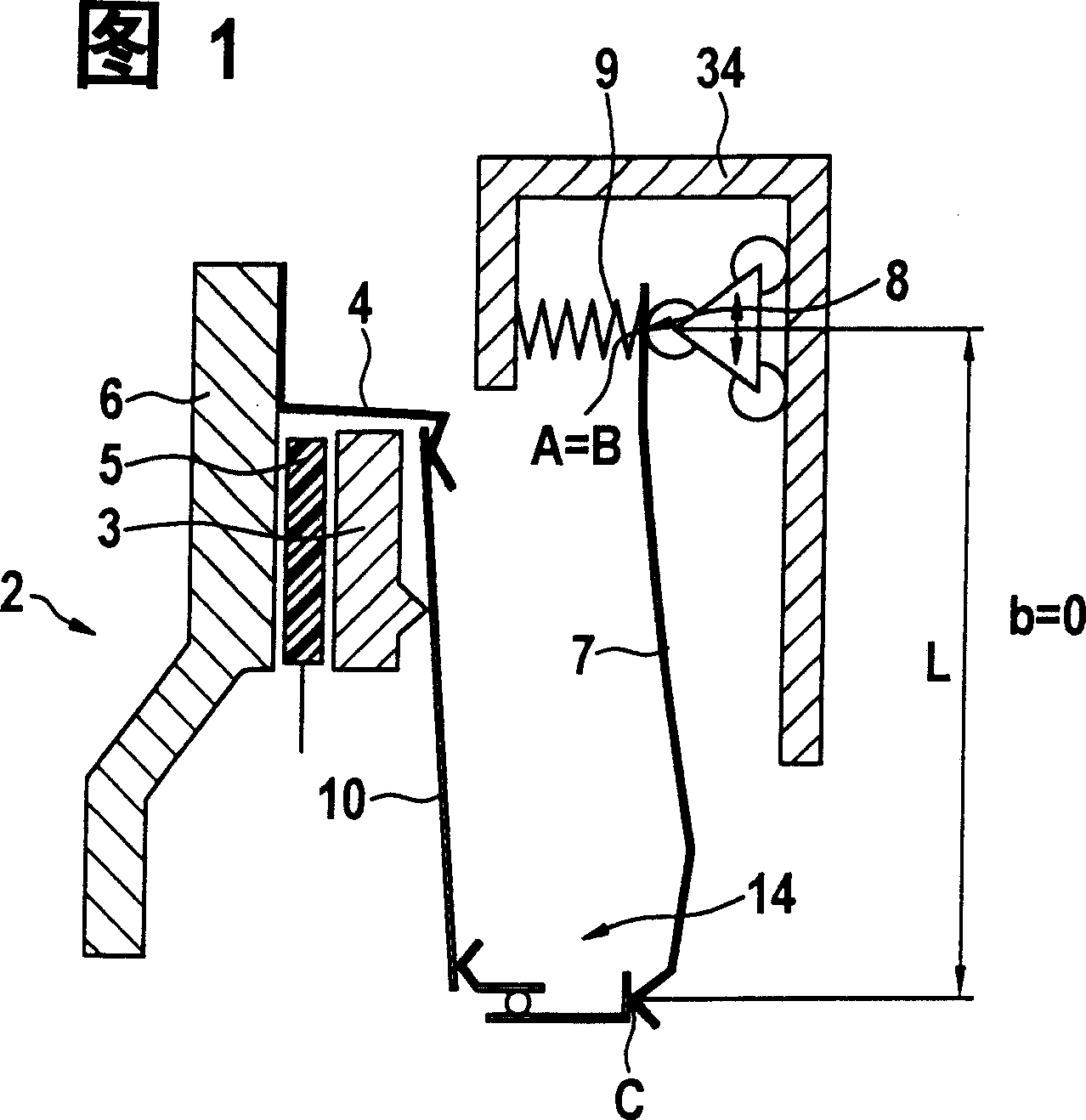
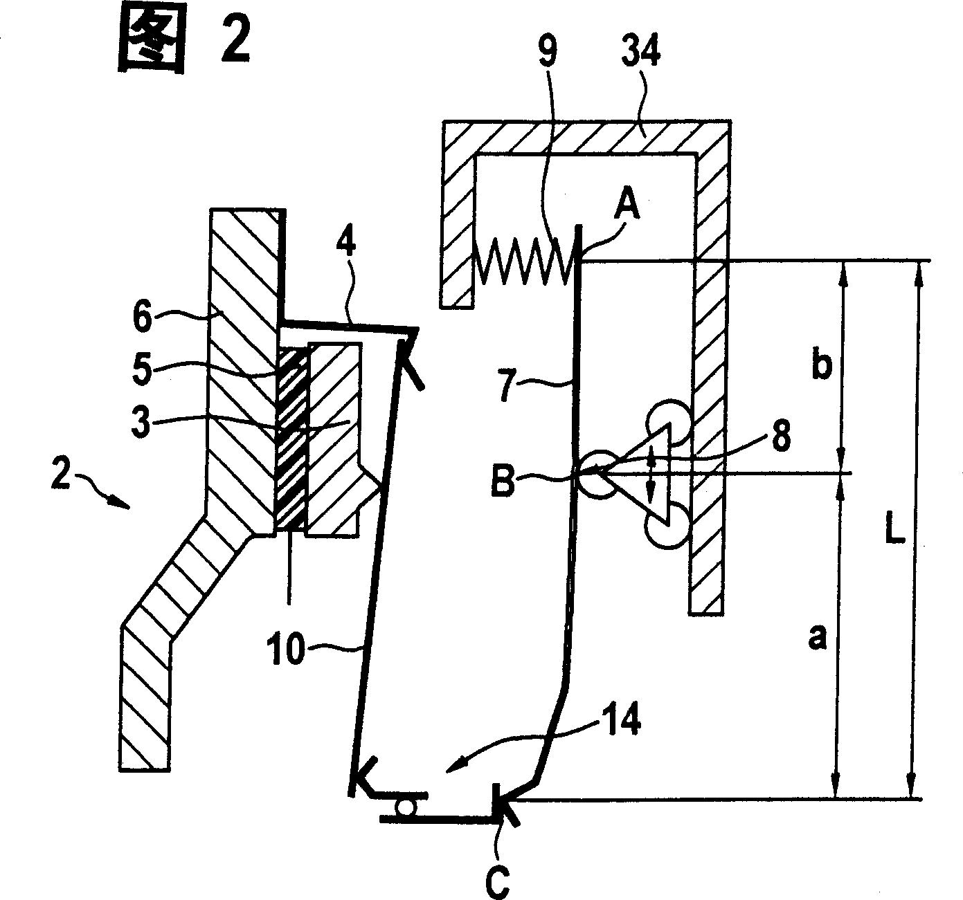
[0062]1 and 2 only schematically show a clutch with an operating mechanism according to the invention. Figure 1 shows an open clutch 2 and Figure 2 shows the same clutch in a closed state. Therefore, Figures 1 and 2 must be observed together in imagination. The clutch 2 basically consists of a counter-pressure plate 6, a clutch disc 5, a pressure plate 3, a clutch cover 4 and a release spring 10, which is constructed here as a disc spring. The operating mechanism for the clutch 2 basically consists of a lever system which is arranged on a bracket 34. The operating mechanism acts via its lever 7 on an axial bearing 14 (which is arranged around a shaft 1 not shown here), wherein t...


PUM


Abstract

A lever system to operate a coupling (2) or brake, especially for a motor vehicle comprises a lever (7) with two sides and a support point (B) which can simultaneously represent a turning point (8). The operating force for the coupling or brake is adjustable through a displacement of the support bearing or turning point.

Description

Technical field [0001] The invention relates to a lever system for operating a clutch or a transmission-brake, which is used in a vehicle, especially a motor vehicle, in which the operating lever system for the lever can be changed. Background technique [0002] According to the prior art, the clutch can be operated, for example, in such a way that a lever with a constant lever length can be operated with an increased force. However, the operation of the clutch can also be achieved through a central separator. The central separator can be driven by an electric motor and directly operated by a cylindrical gear transmission. The disadvantage is that the motor must output its maximum torque to close the clutch. For this it must work at full current. In order not to cause damage to the clutch or the center separator, the electric motor must be braked immediately by an additional brake after the clutch is closed. [0003] In order to open the clutch, the brake must be released beforeh...

Claims


Application Information

Patent Timeline
Patent Type & Authority Applications(China)
IPC IPC(8): F16D13/71F16D23/12F16D23/14F16D55/08F16D65/14
CPCF16D2065/784F16D23/12F16D2300/14F16D2121/24F16D65/567F16D2023/141F16D2125/645F16D65/18F16D2023/126F16D2065/386A63H27/10A63H2027/1058A63H2027/1066A63H2027/1075
Inventor 奥斯瓦尔德·弗里德曼沃尔夫冈·赖克迪尔克·布克哈特沃尔夫冈·哈斯克里斯蒂安·朔伊夫勒拉斯洛·梅恩克里斯托夫·拉贝尔迪尔克·赖姆尼茨马库斯·舍费尔
Owner SCHAEFFLER TECH AG & CO KG
Why Eureka
Try Eureka