Shoe-washing machine
A shoe washing machine and shoe bucket technology, applied in the field of shoe washing machines, can solve the problems of insufficient washing strength and uniformity to achieve shoe washing effect, unsatisfactory cost and performance, uncompact structure, etc. The effect of improving the uniformity of washing and improving the utilization rate
- Summary
- Abstract
- Description
- Claims
- Application Information
AI Technical Summary
Problems solved by technology
Method used
Image

Examples
Embodiment 1
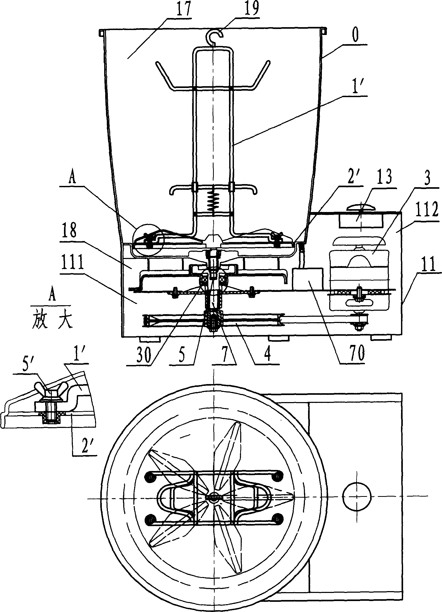
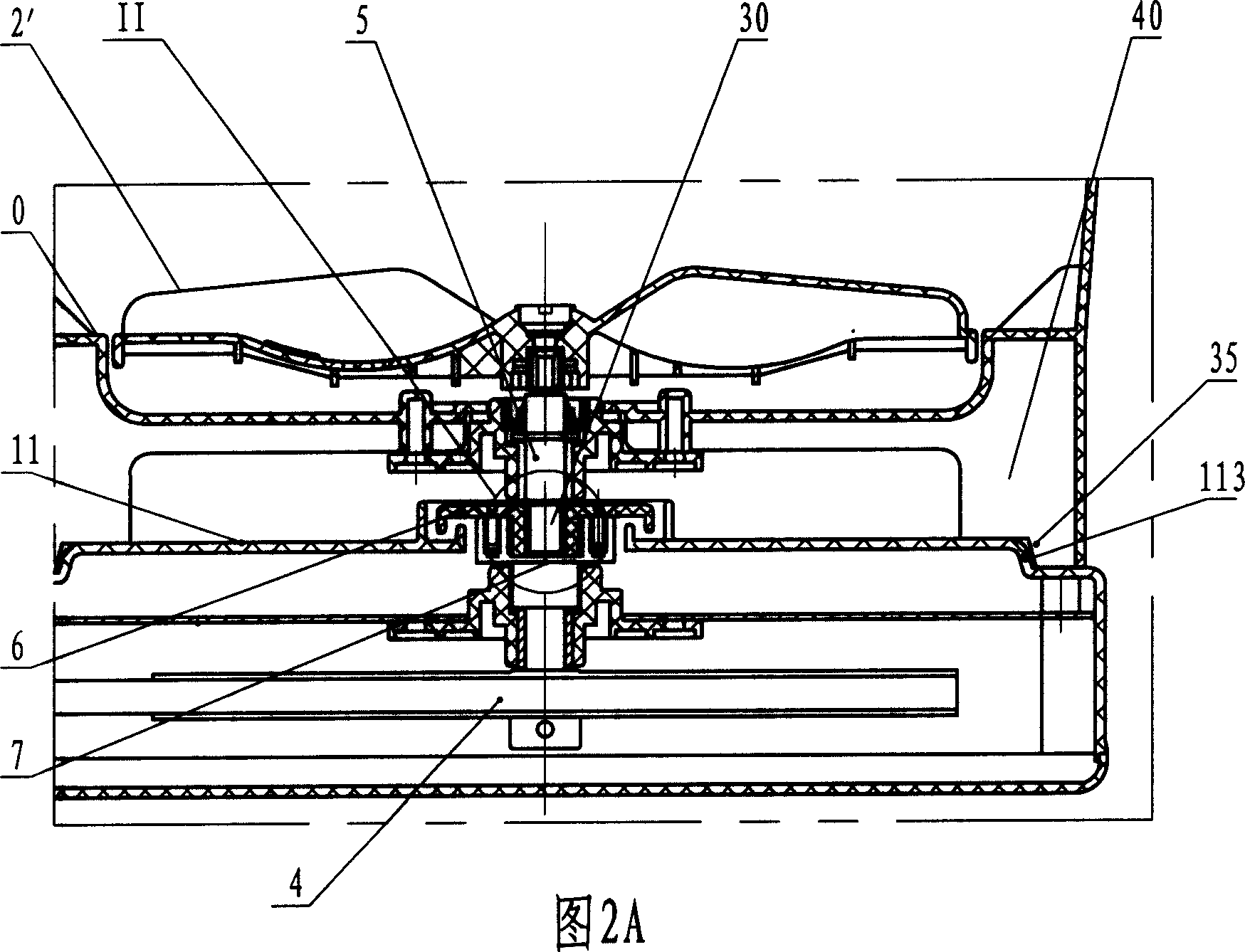
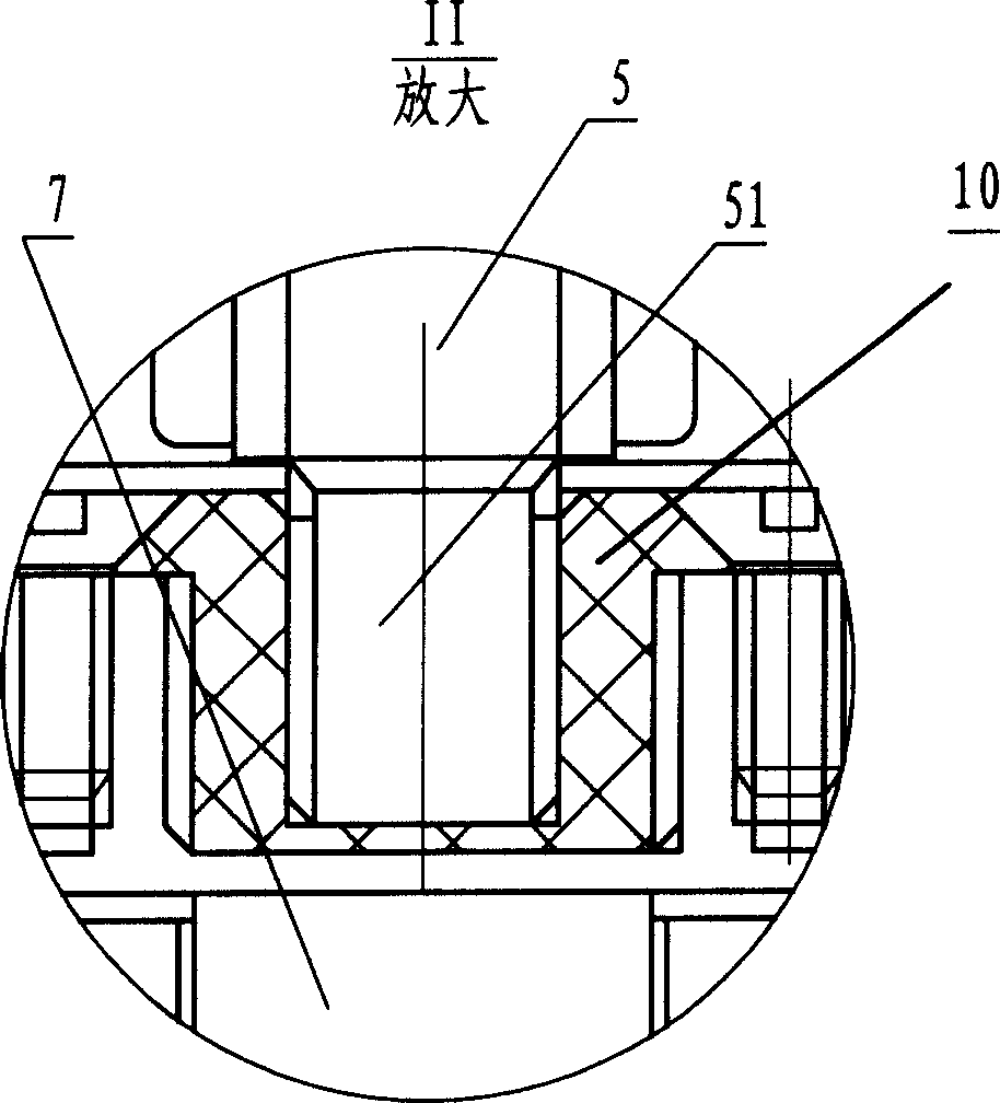
[0037] The shoe washing machine see attached figure 1 , where the shoe is placed is a bracket, such as image 3 Shown: support 1 ' has the hanger that is used for hanging shoes that the fixed support 7 ' that is positioned at stand top and the sliding support 8 ' of bottom form. The sliding support 8' can slide up and down with the stand as the track, and the spring 9' is used to hook the lower crossbar of the stand; the four feet of the support 1' have installation holes 6', and the corresponding positions on the stirring wing 2' are screw holes. When in use, pass the thumb screw 2' through the mounting hole 6' and tighten it in the screw hole, that is, the bracket 1' is fixed to the stirring wing 2'; the shoes are tensioned on the fixed support 7' and the sliding support 8'; due to the placement of the shoes The fixed support 7' and the elastic sliding support 8' have a certain distance from the rotation center of the support. When the motor 3 drives the stirring wing 2' t...
Embodiment 2
[0039] The shoe washing machine see attached Figure 5 , where the shoes are placed is a basket, such as Figure 4 As shown: there is a horizontal interval 7" in the middle of the basket 1", which divides the basket 1" into two chambers 8" for placing shoes, and makes the two chambers 8" a certain distance from the center of rotation; the basket 1" There are hooks 5" and mounting plugs 6" at the bottom. The agitating wing 2" has a locking hole and a positioning hole correspondingly facing the hook 5" and the installation connector 6". When the basket 1" is installed on the agitating wing 2", the hook 5" is stuck on the agitating wing 2" to prevent the basket 1" from falling out, and the installation connector 6" is inserted into the corresponding installation hole of the stirring wing 2", which mainly plays the role of installation positioning and transmission of the movement of the stirring wing 2". The hook 5" and The bottom of the basket 1" is injection-molded as a whole,...
Embodiment 3
[0041] The shoe washing machine see attached Figure 7 , where the shoes are placed is a basket, such as Figure 6 As shown: there is a horizontal interval 7 in the middle of the basket 1, which divides the basket 1 into two chambers 8 for placing shoes, and makes the two chambers 8 a certain distance from the center of rotation; The bottom is two pairs of hooks 5, and each pair of hooks is connected with a half arc, so it has elasticity. The agitating wing 2'' has a locking step correspondingly facing the horizontally extending end of the hook 5''. When the basket 1 is installed on the agitating wing 2, the horizontally extended end of the hook 5 is inserted into the locking step and locked to prevent the basket 1 from coming out. When in use, push point E for each pair of hooks 5 to make the horizontally extending end inserted and retracted, and then reset and insert the step of the agitating wing 2 to be stuck, that is, to install the basket 1 on the agitatin...
PUM
 Abstract
Description
Claims
Application Information
 - R&D
- Intellectual Property
- Life Sciences
- Materials
- Tech Scout
- Unparalleled Data Quality
- Higher Quality Content
- 60% Fewer Hallucinations
Browse by: Latest US Patents, China's latest patents, Technical Efficacy Thesaurus, Application Domain, Technology Topic, Popular Technical Reports.
© 2025 PatSnap. All rights reserved.Legal|Privacy policy|Modern Slavery Act Transparency Statement|Sitemap|About US| Contact US: help@patsnap.com