Ignitor
An appliance, electric ignition technology, applied in the direction of combustion ignition, igniter with fuel, combustion method, etc., can solve the problems of complicated assembly, difficult assembly, small interference part, etc., to improve reliability, reliable locking state, large The effect of moving range
- Summary
- Abstract
- Description
- Claims
- Application Information
AI Technical Summary
Problems solved by technology
Method used
Image
Examples
no. 1 Embodiment approach
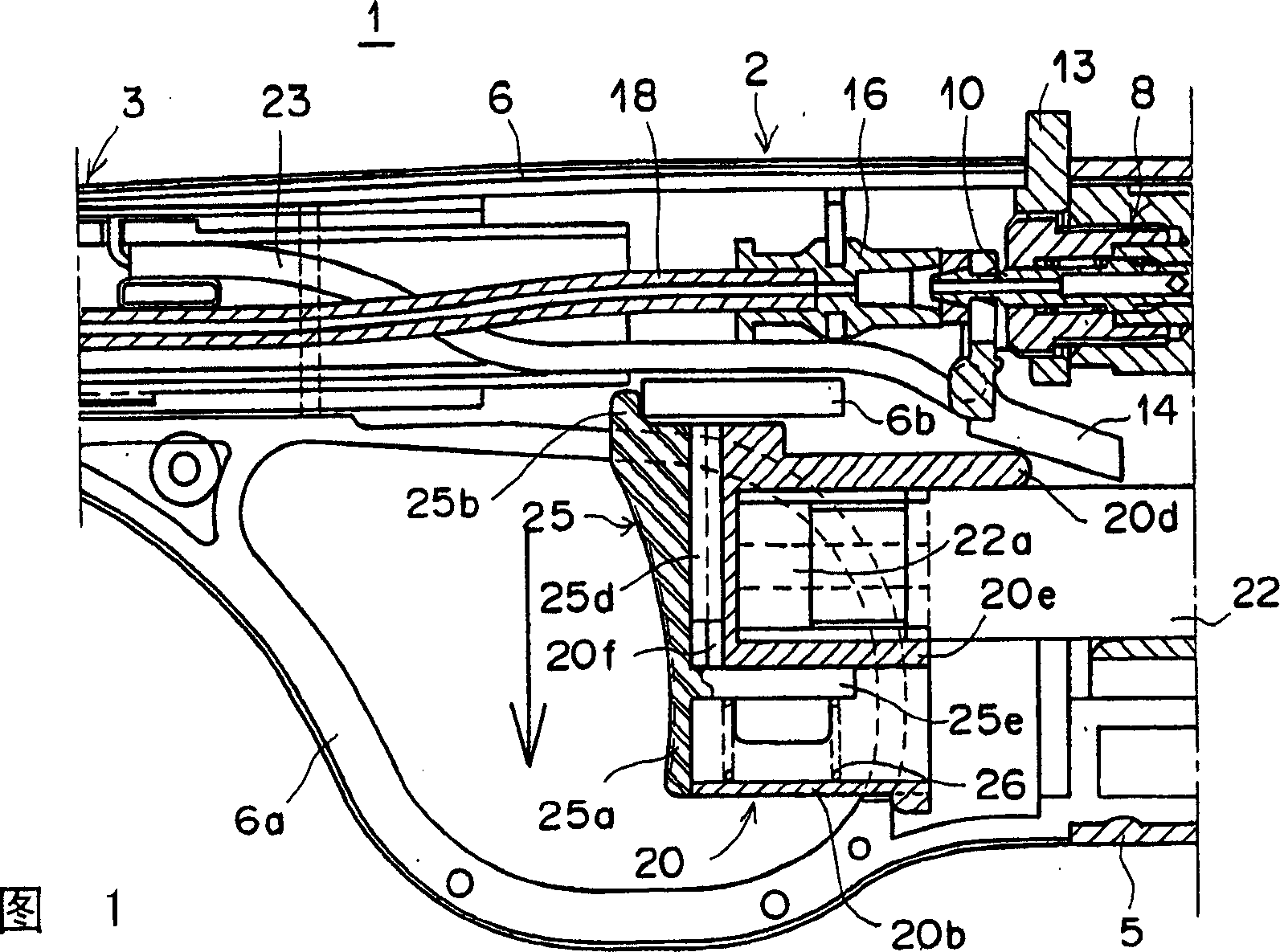
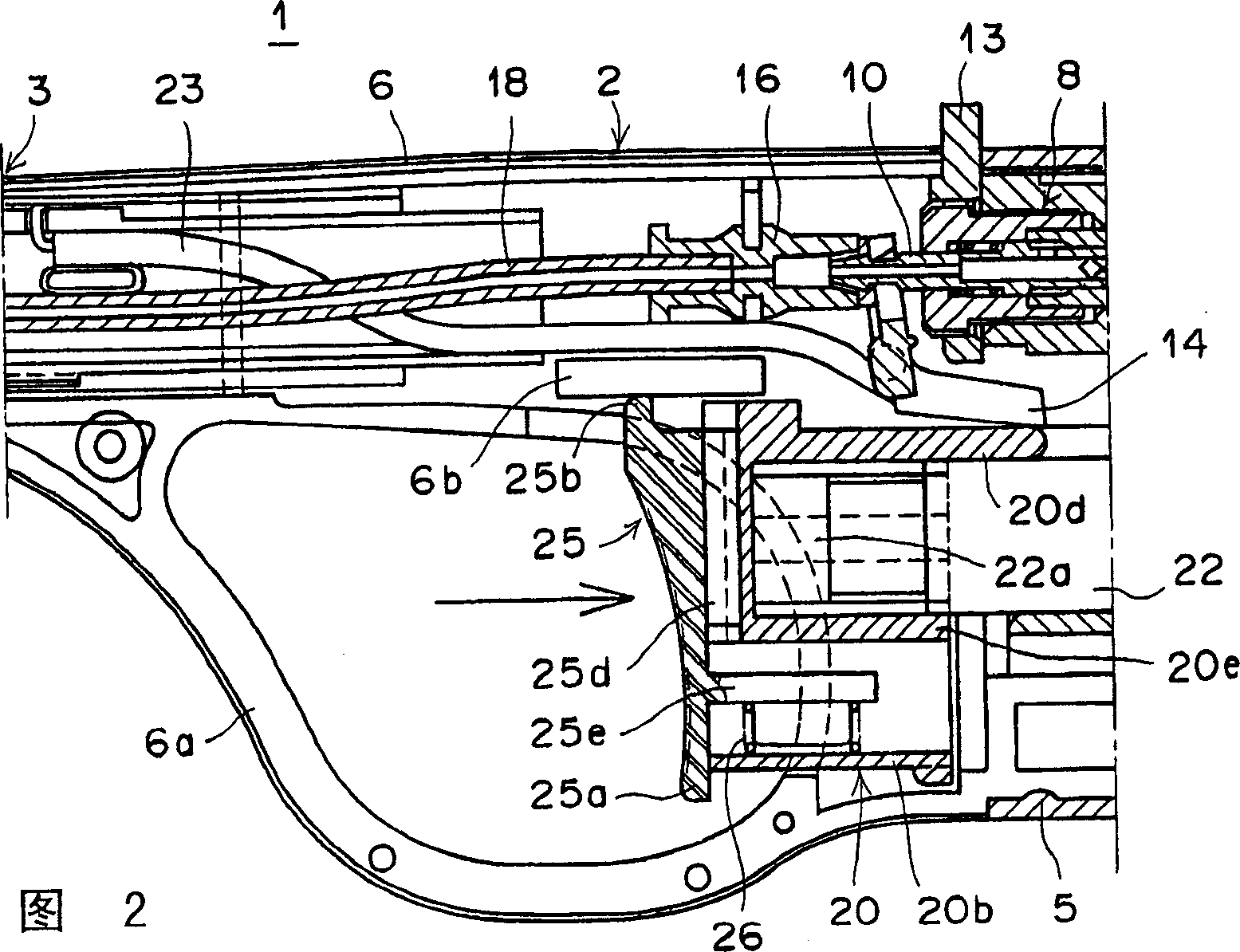
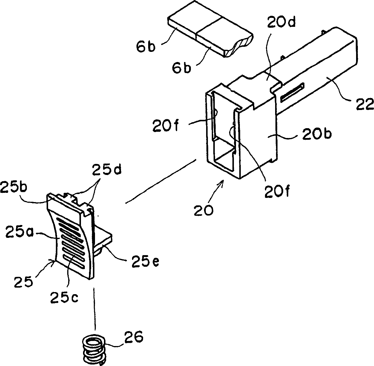
[0034] Figure 1~ Figure 3B Show the igniter that this embodiment is constituted by the ignition rod, Fig. 1 is a sectional view of main parts, Fig. 2 is a sectional view of an operating state, Figure 3A with Figure 3B is an oblique view of the locking mechanism.
[0035] The igniter (ignition rod) 1 of the present embodiment is composed of a device body 2 and an extended tip portion 3 extending in a rod shape (the tip portion is omitted in the figure). The appliance body 2 is formed of a synthetic resin-molded gas storage tank portion 5 and an intermediate case 6. The intermediate case 6 is divided longitudinally at approximately the center in front of the gas storage tank portion 5. FIGS. 1 and 2 show the intermediate case. 6 for one.
[0036] A gas storage chamber (not shown in the figure) is provided on the base end side (right side of the figure) of the appliance body 2 for storing high-pressure gas such as butane gas in the gas storage tank portion 5. A valve mechan...
no. 2 Embodiment approach
[0052] Fig. 4 is a sectional view of main parts of an igniter provided with a locking mechanism of another embodiment; Fig. 5 is a sectional view showing an operating state; Figure 6A with Figure 6B is an oblique view of the locking mechanism.
[0053] The lock mechanism in the igniter 11 of this embodiment is different from that of the first embodiment, except that the lock member 27 and the form of the engaging portion 6c are different, the operating member 20, the piezoelectric assembly 22 (ignition device), and the biasing member 26 are all the same. The configuration is the same, so the same parts are given the same symbols and their descriptions are omitted.
[0054] In this embodiment, the locking position and the unlocking position of the locking member 27 are configured opposite to those of the locking member 25 of the first embodiment described above.
[0055] The locking member 27 also serves as an operating portion of the operating member 20 , is slidable in a ...
no. 3 Embodiment approach
[0063] Figure 7 It is a sectional view of main parts of an igniter equipped with a lock mechanism according to still another embodiment of the present invention, Figure 8 It is a cross-sectional view showing the unlocked state.
[0064] The igniter of this embodiment (another embodiment of the ignition rod) 12 is composed of an appliance body 4 different in shape from the above-mentioned embodiment and a rod-shaped extension front portion 7 extending from the center of the appliance body 4 (the front end portion is omitted in the figure). )constitute. The appliance body 4 is formed of a synthetic resin-molded gas storage tank portion 9 and an intermediate case 60 that is longitudinally divided at the front substantially in the center, Figure 7 with Figure 8 One side of the intermediate case 60 is shown. The intermediate case 60 is formed in a circular shape with a finger insertion window 60a opened in the center.
[0065] The gas storage tank portion 9 on the base end...
PUM
 Abstract
Description
Claims
Application Information
 - R&D
- Intellectual Property
- Life Sciences
- Materials
- Tech Scout
- Unparalleled Data Quality
- Higher Quality Content
- 60% Fewer Hallucinations
Browse by: Latest US Patents, China's latest patents, Technical Efficacy Thesaurus, Application Domain, Technology Topic, Popular Technical Reports.
© 2025 PatSnap. All rights reserved.Legal|Privacy policy|Modern Slavery Act Transparency Statement|Sitemap|About US| Contact US: help@patsnap.com


