
Device of running controlling method for reciprocating dynamic compressor

An operation control and compressor technology, applied in pump control, machine/engine, liquid variable capacity machinery, etc., can solve the problems of inaccurate control, error, and low performance of the motor of reciprocating compressors

Inactive Publication Date: 2004-09-22
LG ELECTRONICS (TIANJIN) APPLIANCES CO LTD
View PDF0 Cites 0 Cited by
  • Summary
  • Abstract
  • Description
  • Claims
  • Application Information

AI Technical Summary

Problems solved by technology

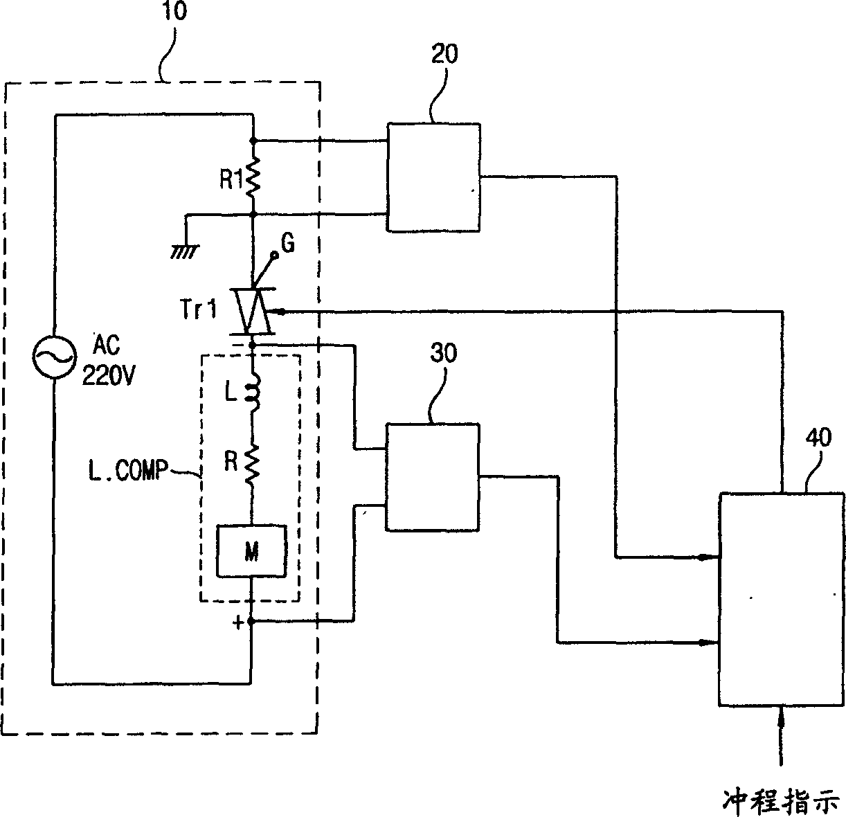
[0013] However, there will be errors in the process of calculating the impulse voltage through the information transmitted from the current detection part and the information from the voltage detection part transmitted to the microprocessor.
[0014] Therefore, the motor of the reciprocating compressor cannot be precisely controlled, resulting in abnormal operation and low performance.

Method used


Image

  • Device of running controlling method for reciprocating dynamic compressor
  • Device of running controlling method for reciprocating dynamic compressor
  • Device of running controlling method for reciprocating dynamic compressor

Examples


Embodiment Construction

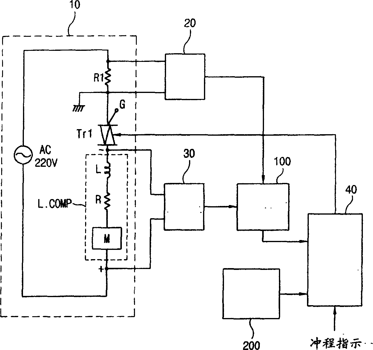
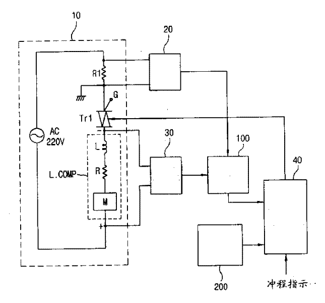
[0030] figure 2 It is a circuit diagram of the device structure suitable for the operation control method of the reciprocating compressor of the present invention. As shown in the figure, its composition is: a current detection part 20 for detecting the current introduced into the motor; detecting the voltage at both ends of the compressor The detection part 30; the stroke calculation part 100 according to the impulse voltage transmitted by the above-mentioned current detection part 20 and the voltage detection part 30; the information transmitted by the above-mentioned stroke calculation part 100 is compared with the stroke indication, and the impact of the error value generated by the compensation is transmitted Voltage compensation part 200; The microprocessor 40 that outputs the switch control signal according to the information output from the above-mentioned stroke calculation part 100 and the impulse voltage compensation part 200; According to the switch control signal ...


PUM


Abstract

A method and device for controlling the running of reciprocating compressor. Said method includes such steps as detecting the input voltage and current of motor, picking up impulse voltage, comparing the impulse voltage with stroke indication, compensating the impulse voltage to a certain value if the impulse voltage is less than stroke indication or lowering the impulse voltage to a certain value if the impulse voltage is more than stroke indication, and outputting drive signal to motor by microprocessor.

Description

technical field [0001] The invention belongs to the field of control or safety equipment for refrigerators and air-conditioning compressors, and relates to a device of a method for controlling the operation of a reciprocating compressor, in particular to detecting the impulse voltage from the current flowing into the motor, compensating the error of the impulse voltage, and suppressing the impact voltage of the motor. A device for improving the operation control method of reciprocating compressors with poor motor performance. Background technique [0002] In general, reciprocating compressors use switch terminals to control the power supplied to the coils wound on multiple stators to generate rotational torque, thereby changing the excitation state between the rotor and the stator, so that positive rotation can be generated by electromagnetic attraction torque. [0003] If, without changing the specific excitation state, the rotor can stay at a certain position, the maximum...

Claims


Application Information

Patent Timeline
Patent Type & Authority Applications(China)
IPC IPC(8): F04B49/06
Inventor 金在浩
Owner LG ELECTRONICS (TIANJIN) APPLIANCES CO LTD
Learn More