Electric valve

A technology of electric valves and valve bodies, which is applied in the direction of lifting valves, valve devices, valve details, etc., and can solve problems such as impact

Active Publication Date: 2004-10-06
FUJIKOKI MFG CO LTD
View PDF1 Cites 21 Cited by
  • Summary
  • Abstract
  • Description
  • Claims
  • Application Information

AI Technical Summary

Problems solved by technology

In such a state, if a noise of several KV is added to the stator coil 53, a discharge may occur between the magnetic pole teeth 51a and the case 40, and when the discharge occurs, the noise may affect the surrounding circuits. Danger

Method used


Image

  • Electric valve
  • Electric valve
  • Electric valve

Examples


no. 1 Embodiment

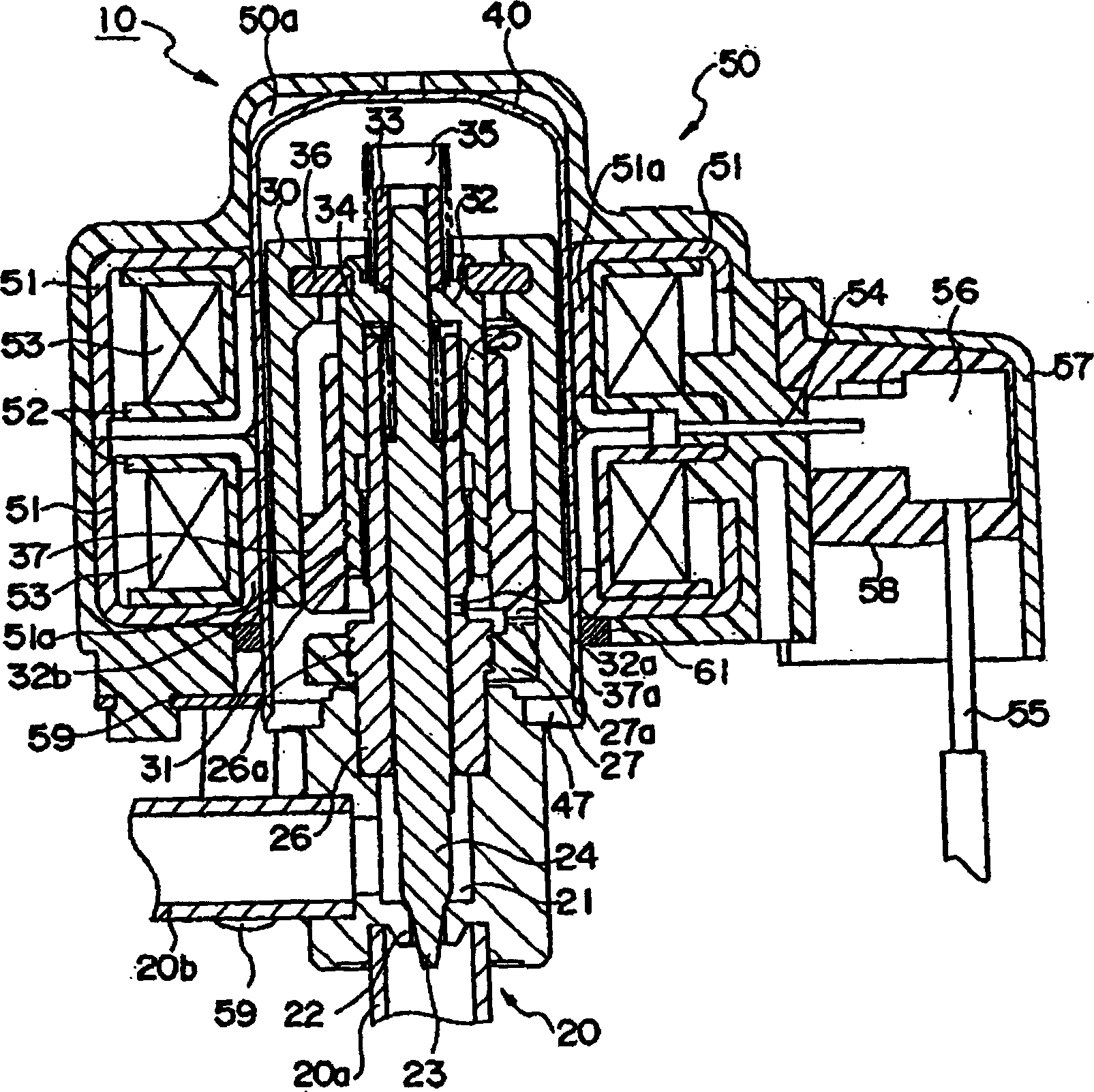
[0028] Embodiments of the electric valve of the present invention will be described in detail below with reference to the accompanying drawings. figure 1 It is a longitudinal sectional view of the electric valve of the first embodiment of the present invention. In this figure, the same components as those of the conventional motor-driven valve shown in FIG. 4 are denoted by the same reference numerals, and description thereof will be omitted. In the first embodiment, a conductive ring 61 made of brass, for example, is fitted on the outer periphery of the case 40 , and the conductive ring 61 is brought into contact with the yoke 51 of the stator 50 . In this way, since the yoke 51 is connected to the valve main body 20 through the conductive ring 61 and the shell 40, even if high-voltage noise is added to the stator coil 53, the discharge generated between the yoke 51 and the shell 40 can be suppressed, and the impact on the yoke 51 can be reduced. effects on surrounding circu...

no. 2 Embodiment

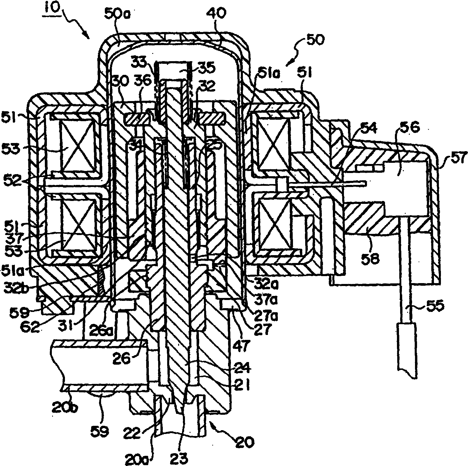
[0030] use figure 2 The structure of the electric valve of the second embodiment of the present invention will be described. In this figure, the same components as those of the conventional electric valve shown in FIG. 4 are given the same reference numerals, and their descriptions are omitted. In this embodiment, the valve body 20 and the yoke 51 are connected using a conductive resin 62 . That is, in this embodiment, the anti-rotation member 59 and the yoke 51 that fix the stator 50 to the case 40 non-rotatably are connected using the conductive resin 62 . Since the anti-rotation member 59 is connected to the fluid lead-out pipe 20b attached to the valve main body 20, similar to the first embodiment, even if high-voltage noise is added to the stator coil 53, the noise generated between the yoke 51 and the case 40 can be suppressed. Discharge can reduce the impact on the surrounding circuit.

no. 3 Embodiment

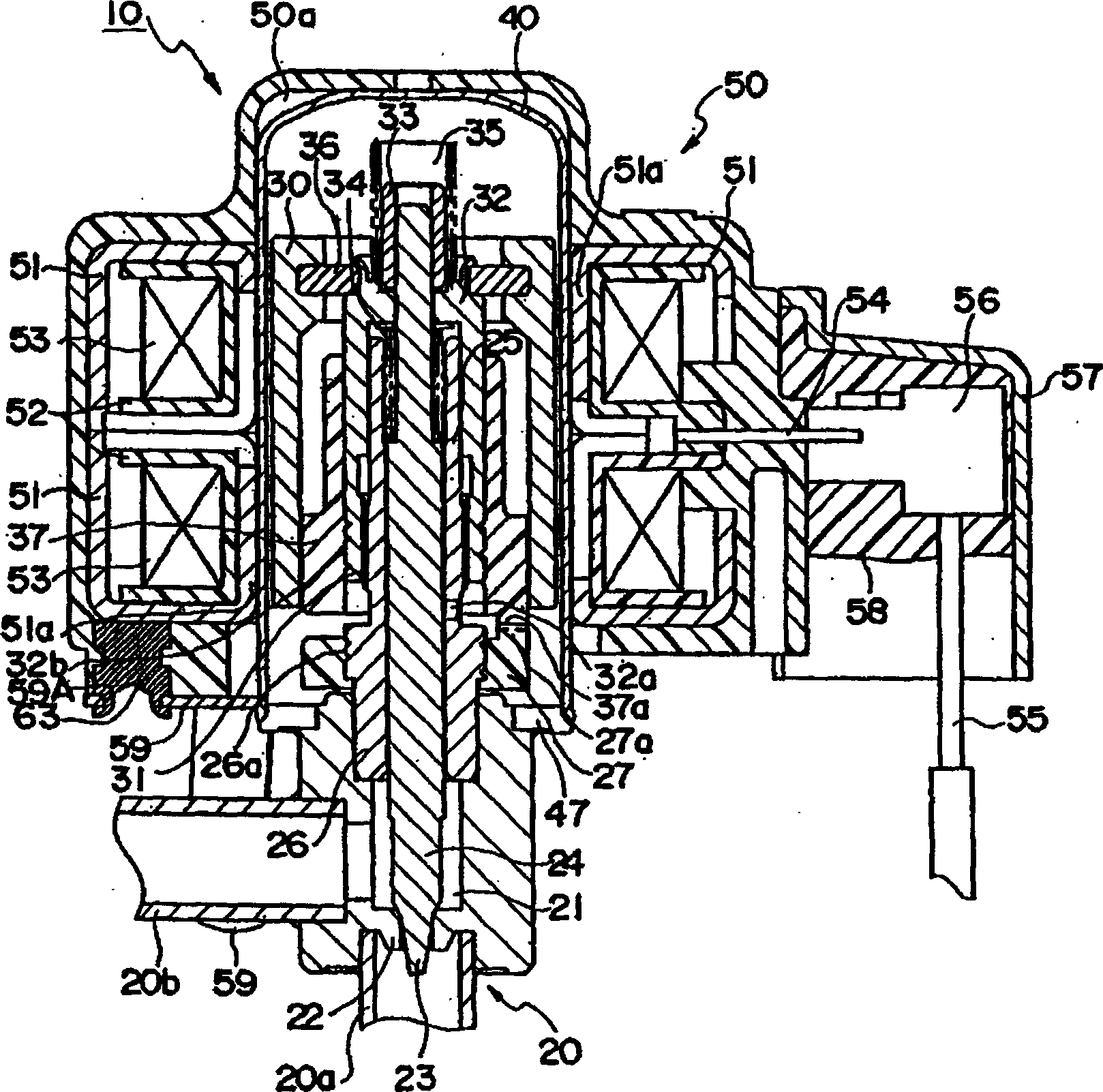
[0032] use image 3 The structure of an electric valve according to a third embodiment of the present invention will be described. In this figure, the same components as those of the conventional electric valve shown in FIG. 4 are given the same reference numerals, and their descriptions are omitted. In this embodiment, the valve body 20 and the yoke 51 are connected by a conductive fixing pin 63 made of conductive material. That is, in this embodiment, the anti-rotation member 59 and the yoke 51 that fix the stator 50 to the case 40 in a non-rotatable manner are connected using, for example, brass conductive fixing pins 63 . Since the anti-rotation member 59 is connected to the fluid outlet pipe 20b, similar to the first embodiment, even if high-voltage noise is added to the stator coil 53, the discharge generated between the yoke 51 and the case 40 can be suppressed, and the impact on the surrounding environment can be reduced. circuit effects.

[0033] As a method of pro...


PUM


Abstract

Provided is a motor operated valve which can reduce effects of noise upon peripheral circuits by suppressing an electric discharge between a can and a stator caused by the noise. A motor operated valve 10 comprises a valve body 20 for controlling a passing flow rate by means of a valve element 23 which comes into contact with a valve seat 22 in a valve chamber 21 via a valve stem 24 and separates from the valve seat 22, a can 40 which is fixed to the valve body 20 and has a built-in rotor 30 for bringing the valve element 23 into contact with the valve seat 22 and for separating the valve element 23 from the valve seat 22, and a stator 50 which is fitted on the can 40 and rotatably drives the rotor 30. A conductive fixing pin 63 is provided on the mold portion of the stator 50 so as to come into contact with a yoke 51. The valve body 20 and the yoke 51 are electrically coupled by fixing a rotation-stopping member 59 to the conductive fixing pin 63 by caulking.

Description

technical field [0001] The present invention relates to an electric valve assembled in an air conditioner, a refrigerator, etc., and particularly relates to an electric valve without discharge between the magnetic pole teeth of a stepping motor and the housing containing the rotor. Background technique [0002] In the prior art, such electric valves used in air conditioners, refrigerators, etc. are devices for regulating the flow of fluids such as refrigerants. Usually, a valve body with a valve chamber and a valve seat is equipped, and is fixed on the valve by a jaw. The upper portion of the valve body is a bottomed cylindrical case, a rotor is built inside the case, and a stator having a through hole in the center is fitted outside the case (see, for example, JP-A-2001-50415). [0003] The structure of the conventional electric valve shown in Unexamined-Japanese-Patent No. 2001-50415 is demonstrated using the cross-sectional view of FIG. The electric valve 10 includes a v...

Claims


Application Information

Patent Timeline
Patent Type & Authority Applications(China)
IPC IPC(8): F16K31/04F16K1/00
CPCY02B30/72E01D19/02E04G13/021H02G3/28
Inventor 大内共存福井和之柿沼真一原田贵雄
Owner FUJIKOKI MFG CO LTD
Why Eureka
Try Eureka