Lighting device for household appliances

A technology for lighting devices and household appliances, which is applied in the direction of household lighting, lighting devices, lighting devices, etc., and can solve problems that cannot be eliminated smoothly

Inactive Publication Date: 2004-10-20
舱壁玻璃公司
View PDF1 Cites 18 Cited by
  • Summary
  • Abstract
  • Description
  • Claims
  • Application Information

AI Technical Summary

Problems solved by technology

The disadvantages of the described installation of the lamp on the side wall cannot be successfully eliminated by means of this support frame structure.

Method used


Image

  • Lighting device for household appliances
  • Lighting device for household appliances

Examples


Embodiment Construction

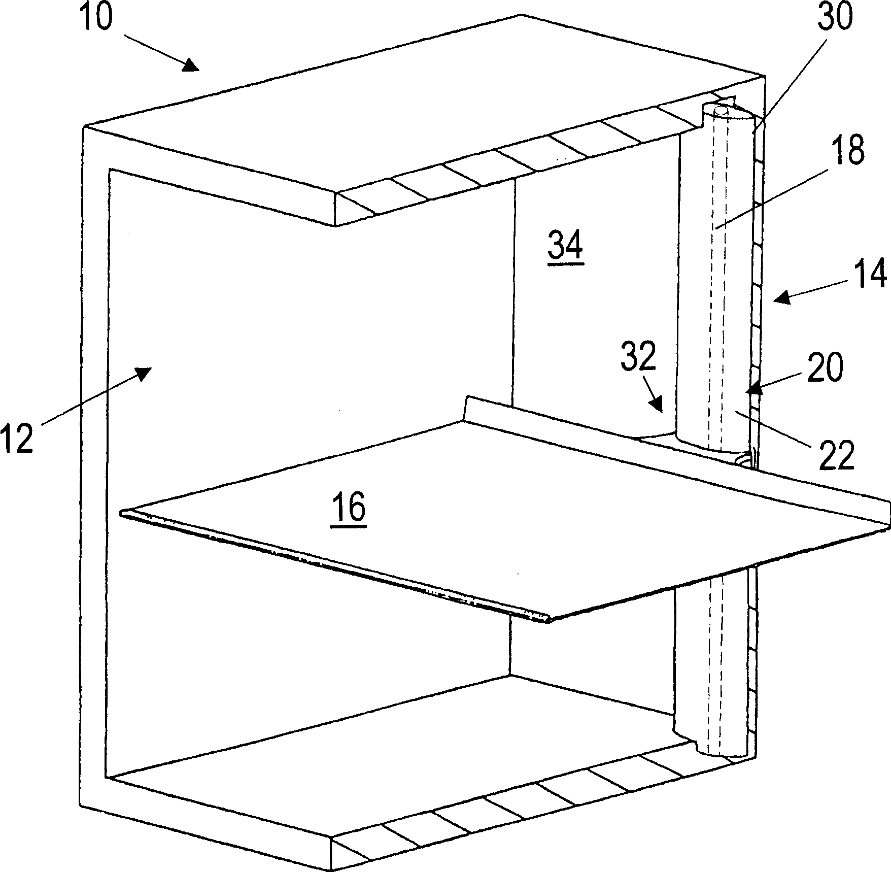
[0018] figure 1 A refrigerator 10 is shown in a partially cutaway perspective view, in which a support frame 14 for mounting a support grid 16 is arranged in its inner chamber. The support frame has a profiled guide rail 30 which is mounted on the inner wall 34 of the rear side of the refrigerator 10 opposite to the door of the refrigerator 10 so as to extend substantially vertically in the inner chamber 12 of the refrigerator 10 . Alternatively, a plurality of vertically extending profiled rails mounted on different side walls of the refrigerator inner chamber may be used.

[0019] A support element 32 for supporting and fixing the support grid 16 is mounted on the profile rail 30 . The support element 32 is displaceable along the profile rail 30 and can be fastened to the profile rail 30 at a desired height by means of detachable fastening elements (not shown in detail).

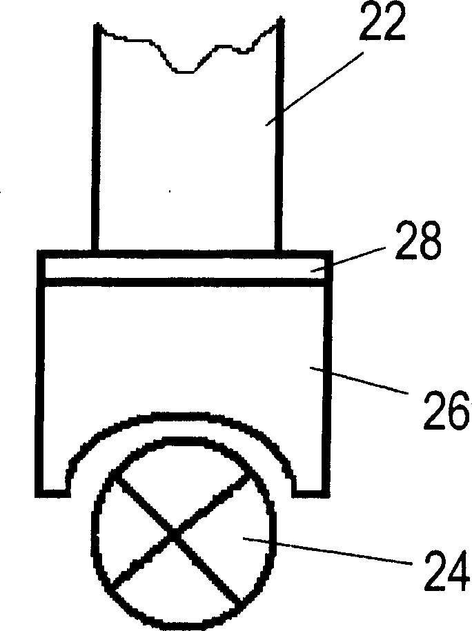
[0020] The profile rail 30 has a transparent hollow body with an essentially oval cross-section, for ...


PUM


Abstract

A lighting installation for household appliances having an interior in which a bracket for receiving support shelves is arranged. The lighting arrangement includes an illuminating device integrated into at least a partial area of the bracket or entirely into the bracket. The illuminating device can include a fluorescent tube or an arrangement of a plurality of light-emitting diodes. Alternatively, at least a partial area of the bracket can be embodied as an optical waveguide, into which the light from a light source not arranged in the interior can be introduced.

Description

technical field [0001] The invention relates to a lighting device for a household appliance. A support frame for installing a support grid is arranged in an inner chamber of the household appliance. Background technique [0002] It is known from the prior art that a lamp is mounted on the side wall of the interior of the refrigerator in order to illuminate the interior of the refrigerator. The light is switched on when the refrigerator door is opened by means of a contact. Mounting the lights on the side walls however has the disadvantage that large refrigerated food containers or packaged food can obscure the lights. Because refrigerated food occupies (shades) most of the space in the refrigerator interior cavity, this results in a significant reduction in illuminance. Since it is known that the lamps used are generally incandescent lamps, it is also a disadvantage that the heat generated by the incandescent lamps disadvantageously heats the cooling chamber. [0003] Fro...

Claims


Application Information

Patent Timeline
Patent Type & Authority Applications(China)
IPC IPC(8): F21V9/08F21V33/00F21W131/305F21Y101/02F21Y103/00F25D25/02F25D27/00H01L33/00H01L33/50
CPCF21V33/0044F25D27/00F21Y2101/02F25D2325/022F25D25/02F21W2131/305F21Y2115/10
Inventor 斯蒂芬·休伯特沃纳·亨克尔
Owner 舱壁玻璃公司
Why Eureka
Try Eureka