Semiconductor dehumidifier

A semiconductor and dehumidifier technology, applied in the direction of refrigerators, mechanical equipment, machine operation modes, etc., can solve the problems of refrigerant destroying the ozone layer, environmental pollution, waste of resources, etc., to achieve enhanced dehumidification effect, good heat transfer effect, reduce The effect of heat radiation

Active Publication Date: 2016-07-13
广州市雷子克电气机械有限公司
View PDF7 Cites 16 Cited by
  • Summary
  • Abstract
  • Description
  • Claims
  • Application Information

AI Technical Summary

Problems solved by technology

However, such equipment has large volume, high energy consumption, and high price, and the refrigerant will destroy the ozone layer and cause environmental pollution.
In addition, liquid absorbents, solid adsorbents, etc. are used to dehumidify chemically, but this type of dehumidification is usually used for one-time use, which is likely to cause waste of resources and exhaust chemicals. , impact on the environment

Method used


Image

  • Semiconductor dehumidifier
  • Semiconductor dehumidifier
  • Semiconductor dehumidifier

Examples


Embodiment 1

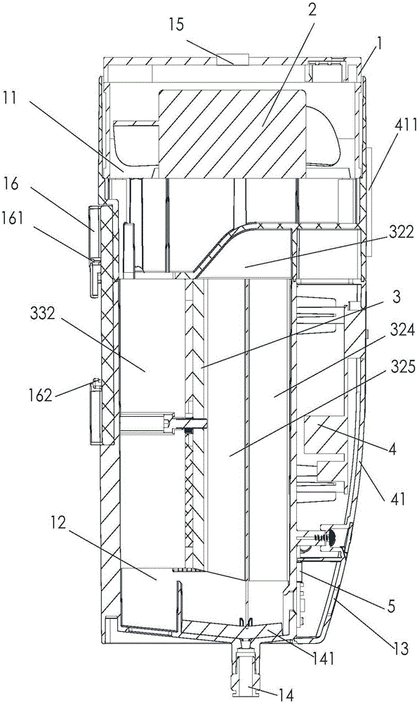
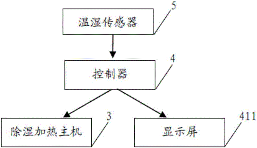
[0039] refer to figure 1 , a semiconductor dehumidifier, including a chassis 1, an exhaust fan 2, a dehumidification heating host 3, a controller 4 and a temperature and humidity sensor 5, the chassis 1 includes a first chamber 11, a second chamber 12, and a chassis air inlet 13 , the cabinet drain port 14 and the cabinet air exhaust port 15; the first chamber 11 is arranged above the second chamber 12; the exhaust fan 2 is installed in the first chamber 11; the dehumidification and heating host 3 is installed In the second chamber 12; the cabinet air inlet 13 is arranged at the lower end of the side wall of the cabinet 1 and communicates with the second chamber 12; the cabinet drain 14 is arranged at the bottom of the cabinet 1; the cabinet drains Water-absorbent cotton 141 is laid on the mouth 14; the cabinet air outlet 15 is installed on the upper end of the first chamber 11, and communicates with the first chamber 11; the controller 4 is installed on the side of the cabine...

Embodiment 2

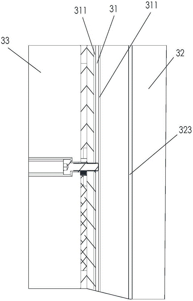
[0045] refer to Figure 4 and combine Figure 5 , the feature of this embodiment is that: the cold end radiator 32 also includes several first fins 326; the several first fins 326 are vertically installed on the surface of the first fixing plate 321; the several first fins 326 A fin 326 is arranged at intervals and extends along the wind direction in the cold end radiator 32; the hot end heater 33 includes a plurality of second fins 333; the plurality of second fins 333 are vertically installed on the second fixed plate 331; the plurality of second fins 333 are arranged at intervals and extend along the wind direction of the hot end heater 33.

[0046] All the other structures and parameters are the same as in Example 1.

[0047] Both the first fins 326 and the second fins 333 can increase the contact surface with the air, the heat transfer effect is better, the efficiency of dehumidification and heating is higher, and the electric power consumed by the semiconductor dehumid...

Embodiment 3

[0049] The feature of this embodiment is that: the first fin 326 is coated with a thermally conductive material layer; the thermally conductive material layer is silicon carbide; other structures and parameters are the same as those in Embodiment 2.

[0050] The heat-conducting material layer can improve the heat transfer effect of the first fins 326 and further enhance the cooling and dehumidification effect of the air.


PUM


Abstract

The invention discloses a semiconductor dehumidifier which comprises a machine case, an exhaust fan, a dehumidifying heating host and a controller.The machine case comprises a first chamber, a second chamber, a machine case air inlet, a machine case water drain outlet and a machine case air outlet.The exhaust fan is installed in the first chamber.The dehumidifying heating host is installed in the second chamber.The machine case air inlet is formed in the lower end of the side wall of the machine case and communicated with the second chamber.The machine case water drain outlet is formed in the bottom of the machine case.The machine case air outlet is installed in the upper end of the first chamber and communicated with the first chamber.The controller is installed on the side face of the machine case.According to the semiconductor dehumidifier, a hot end and a cold end are formed after a semiconductor refrigeration piece of the dehumidifying heating host is powered on; air is cooled through the cold end, and therefore the dehumidifying effect is achieved; air is heated through the hot end, and therefore it is avoided that the air temperature is too low during dehumidifying.

Description

technical field [0001] The invention relates to the field of gas treatment, in particular to a semiconductor dehumidifier. Background technique [0002] At present, it is necessary to maintain a suitable temperature and humidity in daily life, even in electrical appliances, experimental instruments, and storage of articles. Among them, the control of temperature and humidity by instruments needs to be more precise. Too high or too low temperature and humidity will seriously affect the power supply. The service life of the electrical components in the cabinet and the overall operation stability of the cabinet must rely on the cabinet heater and the dehumidifier in the cabinet to accurately control the environment of the cabinet. The dehumidification equipment on the market at this stage mainly adopts the cooling method of mechanical air compressor. However, such equipment has large volume, high energy consumption, and high price, and the refrigerant will destroy the ozone la...

Claims


Application Information

Patent Timeline
Patent Type & Authority Applications(China)
IPC IPC(8): F25B21/02F24F3/14F28F3/04F24F11/00
CPCF24F3/14F24F11/30F24F2003/144F24F2110/00F24F2110/10F24F2110/20F25B21/02F28F3/04
Inventor 高强东
Owner 广州市雷子克电气机械有限公司
Why Eureka
Try Eureka