Illumination device and projector equipping the same

a technology of a projector and a device, which is applied in the field of illumination devices and projectors equipping the same, can solve the problems opacity and expansion wear of the electrode, etc., and achieves the effect of shortening the service life of the light-emitting tube and reducing heat radiation

Inactive Publication Date: 2006-06-13
SEIKO EPSON CORP
View PDF9 Cites 15 Cited by
  • Summary
  • Abstract
  • Description
  • Claims
  • Application Information

AI Technical Summary

Benefits of technology

[0005]However, when the auxiliary second reflecting mirror is mounted on the light-emitting tube so as to surround the periphery of the light-emitting member of the light-emitting tube, the second reflecting mirror acts to reduce heat radiation from the light-emitting tube. Therefore, the problem is that the temperature of the light-emitting tube had a nonuniform distribution and the temperature is greatly increased locally, thereby causing wear of electrodes, opacity and expansion of the light-emitting tube, and shortening of service life of the light-emitting tube.
[0006]The invention was developed to address the aforementioned problems, and in an aspect provides an illumination device including a light-emitting tube, a first reflecting mirror which is the main reflecting mirror for the light emitted from the light-emitting tube, and a transparent plate disposed in the distal end portion of the first reflecting mirror. This illumination device includes the light-emitting tube in which the degradation of service life and reliability caused by the second reflecting mirror can be reduced or prevented even when the second reflecting mirror, which is the auxiliary reflecting mirror, is disposed so as to surround the periphery of the light-emitting member of the light-emitting tube. An aspect of the invention also provides a projector including such an illumination device.
[0007]The illumination device in accordance with an aspect of the invention is an illumination device including a light-emitting tube having a light-emitting member and sealing members located on both sides of the light-emitting member, the light emitting-member including a pair of electrodes, light emission is carried out between the pair of electrodes, a first reflecting mirror to hold the light-emitting tube, reflect the light emitted from the light-emitting tube, and direct the light forward, and a transparent plate disposed in the distal end portion of the first reflecting mirror, the illumination device includes a second reflecting mirror that encloses a front portion of the light-emitting member and reflects the light from the light-emitting member toward the first reflecting mirror, the second reflecting mirror is fixedly attached to at least one of the sealing member and the transparent plate, the transparent plate and the second reflecting mirror are brought into contact or fixedly attached to each other, and at least one of the transparent plate and the second reflecting mirror is brought into contact or fixedly attached to the sealing member. As a result, most of the light from the light-emitting tube that usually became stray light can be returned to the first reflecting mirror via the second reflecting mirror and supplied for use and the heat of the light-emitting tube can be radiated by heat conduction to the transparent plate or via the second reflecting mirror to the transparent plate, thereby making it possible to prevent or reduce the increase in temperature of the light-emitting tube even if heat generation caused by the installation of the second reflecting mirror is increased.

Problems solved by technology

Therefore, the problem is that the temperature of the light-emitting tube had a nonuniform distribution and the temperature is greatly increased locally, thereby causing wear of electrodes, opacity and expansion of the light-emitting tube, and shortening of service life of the light-emitting tube.

Method used


Image

  • Illumination device and projector equipping the same
  • Illumination device and projector equipping the same
  • Illumination device and projector equipping the same

Examples


exemplary embodiment 1

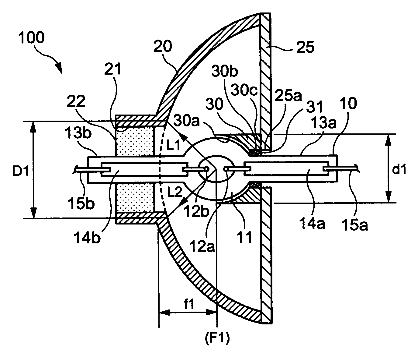
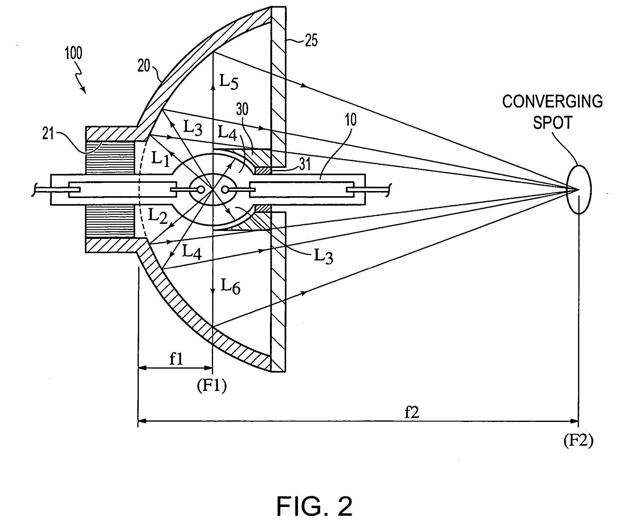
[0033]FIG. 1 is a schematic of an illumination device 100 of exemplary Embodiment 1 of the invention. FIG. 2 is a schematic illustrating the operation of the device 100 shown in FIG. 1.

[0034]The illumination device 100 includes a light-emitting tube 10, a first reflecting mirror 20 which is the main reflecting mirror of the illumination device 100, a transparent plate 25, and a second reflecting mirror 30 which is an auxiliary reflecting mirror of the illumination device 100. The light-emitting tube 10 is made from a quartz glass or the like and includes inside thereof a pair of tungsten electrodes 12, 12, a central light-emitting member 11 having mercury, rare gas, and a small amount of a halogen sealed therein, a sealing member 13a located in front of the light-emitting member 11 and a sealing member 13b located behind the light-emitting member so as to sandwich the light-emitting member 11. Metal foils 14a, 14b composed of molybdenum and connected to a pair of electrodes 12a, 12b...

exemplary embodiment 2

[0054]FIG. 3 is a schematic of an illumination device 100A of exemplary Embodiment 2. The configuration of the illumination device 100A is basically identical to that of the illumination device 100 of exemplary Embodiment 1 shown in FIG. 1 and FIG. 2 and differs from the illumination device 100 of exemplary Embodiment 1 in the following aspects.

[0055]Both a through orifice 25a of the transparent plate 25 and a through orifice 30b of the second reflecting mirror 30 are fixedly attached and fixed to the sealing member 13a of the light-emitting tube 10 with the adhesive 31.

[0056]With the configuration of exemplary Embodiment 2, in addition to the effect of the above-described exemplary Embodiment 1, heat is radiated because heat from the light-emitting tube 10 is conducted directly to the transparent plate 25 via the adhesive 31. Therefore, the surface area through which heat is conducted from the light-emitting tube 10 is enlarged with respect to that of exemplary Embodiment 1, thereb...

exemplary embodiment 3

[0057]FIG. 4 is a schematic of an illumination device 100B of exemplary Embodiment 3. The configuration of the illumination device 100B is basically identical to that of the illumination device 100 of exemplary Embodiment 1 shown in FIG. 1 and FIG. 2 and differs from the illumination device 100 of exemplary Embodiment 1 in the following aspects.

[0058]The second reflecting mirror 30 and the transparent plate 25 are fixed by fixedly attaching the surface 30c of the second reflecting mirror 30 to the transparent plate 25, with the adhesive 31. The transparent plate 25 and light-emitting tube 10 are fixed to each other by fixedly attaching the through orifice 25a of the transparent plate 25 to the sealing member 13a of the light-emitting tube 10 via the adhesive 31. The second reflecting mirror 30 and the light-emitting tube 10 are not in contact with each other.

[0059]With exemplary Embodiment 3, heat from the light-emitting tube 10 is radiated by heat conduction to the transparent plat...


PUM


Abstract

An illumination device including a light-emitting tube having a light-emitting member in which light emission is carried out between a pair of electrodes and sealing members located on both sides of the light-emitting member, a first reflecting mirror to hold the light-emitting tube, reflect the light emitted from the light-emitting tube, and direct the light forward, and a transparent plate disposed in a distal end portion of the first reflecting mirror, a second reflecting mirror that encloses a front portion of the light-emitting member and reflects the light from the light-emitting member toward the first reflecting mirror being fixed to at least one of the sealing member and the transparent plate, the transparent plate and the second reflecting mirror are brought into contact or fixedly attached to each other, and at least one of the transparent plate and the second reflecting mirror is brought into contact or fixedly attached to the sealing member.

Description

BACKGROUND OF THE INVENTION[0001]1. Field of Invention[0002]The present invention relates to an illumination device including a light-emitting tube and a reflecting mirror to reflect the light emitted from the light-emitting tube, and to a projector using such an illumination device.[0003]2. Description of Related Art[0004]Illumination devices composed of a light-emitting tube and a reflecting mirror to direct the light emitted from the light-emitting tube in the prescribed direction have been widely used as illumination devices. In such illumination devices, an auxiliary second reflecting mirror have been provided in a position opposite to the aforementioned reflecting mirror so as to sandwich the light-emitting tube, as described in JP-A-8-31382 (page 2, FIG. 1), in order to effectively use the light that was emitted from the light-emitting tube but became a stray light and could not be supplied for use.SUMMARY OF THE INVENTION[0005]However, when the auxiliary second reflecting mi...

Claims


Application Information

Patent Timeline
Patent Type & Authority Patents(United States)
IPC IPC(8): F21K7/00F21K99/00F21K2/00F21Y101/00G03B21/20H04N9/31
CPCH04N9/3144G03B21/2026H04N9/3197H01J61/86G03B21/16
Inventor TAKEZAWA, TAKESHI
Owner SEIKO EPSON CORP
Why Eureka
Try Eureka