Refrigerating system of low-temperature superconducting magnet

A low-temperature superconducting and refrigeration system technology, which is applied in the direction of superconducting magnets/coils, magnetic objects, electrical components, etc., can solve the problems of low operability and maintainability, poor economy, and difficult disassembly of cold heads of refrigerators, etc. question

Active Publication Date: 2021-06-25
HIWING TECH ACAD OF CASIC
View PDF28 Cites 14 Cited by
  • Summary
  • Abstract
  • Description
  • Claims
  • Application Information

AI Technical Summary

Problems solved by technology

If the first scheme is adopted, as mentioned above, a large amount of liquid helium will be wasted when cooling from 77K to 4.2K, and the economy is poor; if the second scheme is adopted, the consumption of liquid helium is less than that of the first scheme , but in superconducting magnets, heat radiation of cold shields and current leads are one of the main sources of heat leakage. Although liquid helium can be effectively reduced in the cooling process of low-temperature superconducting magnets, due to Refrigerators cannot be carried in high-speed and high-overload environments. Therefore, during the operation of superconducting magnets, components such as cold shields and current leads do not have active refrigeration devices. Due to excessive heat leakage in the system, liquid helium will evaporate too quickly. problem, which may cause superconducting magnets to quench
Another disadvantage of the second solution is that it is difficult to disassemble the cold head of the refrigerator, and the operability and maintainability are low.

Method used


Image

  • Refrigerating system of low-temperature superconducting magnet
  • Refrigerating system of low-temperature superconducting magnet
  • Refrigerating system of low-temperature superconducting magnet

Examples


Embodiment Construction

[0023] It should be noted that, in the case of no conflict, the embodiments in the present application and the features in the embodiments can be combined with each other. The following will clearly and completely describe the technical solutions in the embodiments of the present invention with reference to the accompanying drawings in the embodiments of the present invention. Obviously, the described embodiments are only some, not all, embodiments of the present invention. The following description of at least one exemplary embodiment is merely illustrative in nature and in no way taken as limiting the invention, its application or uses. Based on the embodiments of the present invention, all other embodiments obtained by persons of ordinary skill in the art without creative efforts fall within the protection scope of the present invention.

[0024] It should be noted that the terminology used here is only for describing specific implementations, and is not intended to limit t...


PUM

PropertyMeasurementUnit
critical temperatureaaaaaaaaaa

Abstract

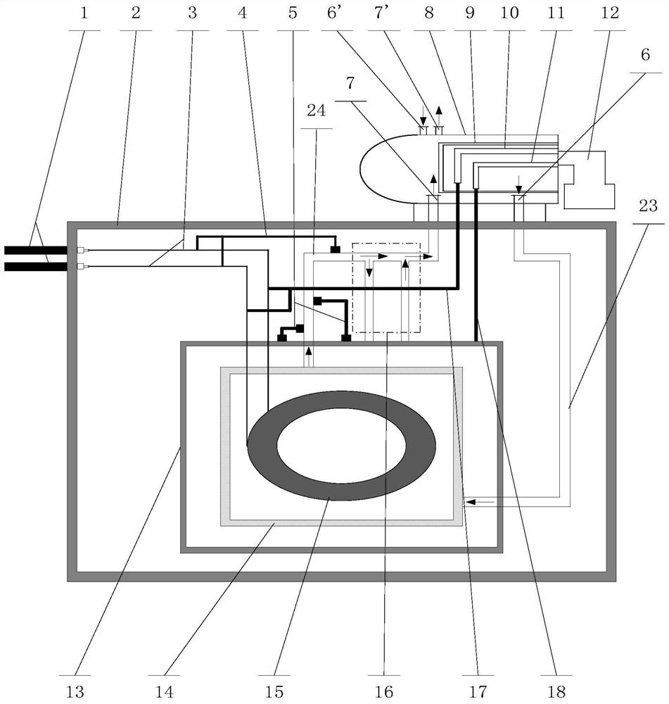
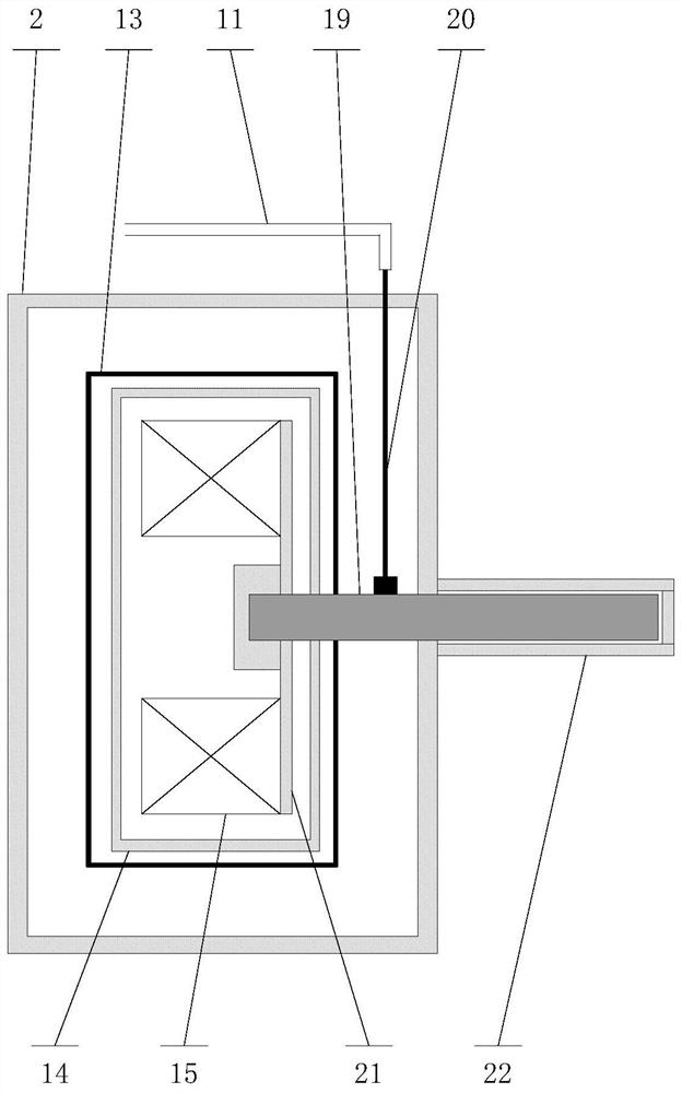
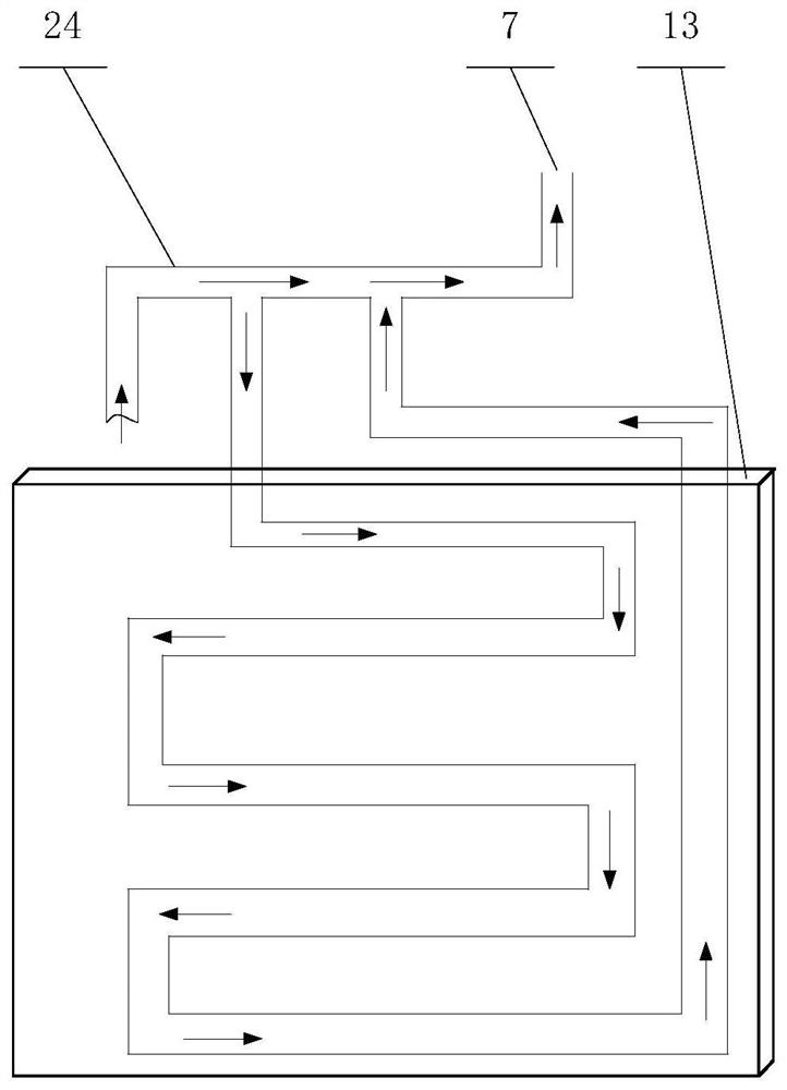
The invention belongs to the technical field of superconducting power application, and discloses a refrigerating system of a low-temperature superconducting magnet. The refrigerating system comprises a cold shield, a lead cooling channel, a cold shield cooling channel, a first liquid helium input opening, a first helium output opening, a helium tank, a liquid helium input pipe and a helium output pipe; the cold shield is arranged outside a low-temperature superconducting coil; the helium tank is arranged between the cold shield and the low-temperature superconducting coil and does not make contact with the cold shield and the low-temperature superconducting coil; the liquid helium input pipe and the helium output pipe are both connected with the helium tank; liquid helium is injected into the helium tank from the first liquid helium input opening through the liquid helium input pipe; helium volatilized from the helium tank is output from the first helium output opening through the helium output pipe; the lead cooling channel is connected between the helium output pipe and a superconducting current lead and is used for guiding cold to cool the superconducting current lead; the cold shield cooling channel is connected between the helium output pipe and the cold shield and is used for conducting cold to cool the cold shield. Therefore, volatilization of liquid helium can be effectively reduced, and the risk of quenching of the low-temperature superconducting magnet is reduced.

Description

technical field [0001] The invention relates to the technical field of superconducting power application, in particular to a refrigeration system for a low-temperature superconducting magnet. Background technique [0002] Superconducting magnets are often used in superconducting power applications, such as medical nuclear magnetic resonance systems and superconducting linear motors, due to their many advantages such as large magnetic field, small size, light weight and low loss. Superconducting magnets can be divided into high-temperature superconducting magnets and low-temperature superconducting magnets according to different raw materials. High-temperature superconducting magnets are generally made of superconducting tapes such as YBCO and GdBCO, and generally work in the liquid nitrogen temperature zone, that is, 77K. In special applications, in order to further improve the current-carrying capacity of high-temperature superconducting materials, they can also work in the...

Claims


Application Information

Patent Timeline
Patent Type & Authority Applications(China)
IPC IPC(8): H01F6/04
CPCH01F6/04Y02B30/00
Inventor 周伟刘伟翟茂春毛凯张艳清韩树春李超吕民东胡道宇邹玲龚珺刘坤
Owner HIWING TECH ACAD OF CASIC
Why Eureka
Try Eureka