Multi tube-fins liquid-air heat exchanger and methods

a heat exchanger and liquid air technology, applied in indirect heat exchangers, lighting and heating apparatuses, heating types, etc., can solve the problems of high installation labor cost, large air duct volume, and ineffective heat transfer efficiency improvement, so as to prevent heat leakage, save system energy, and waste over 20% of energy

Inactive Publication Date: 2011-02-24
PUN JOHN YENKAI
View PDF10 Cites 3 Cited by
  • Summary
  • Abstract
  • Description
  • Claims
  • Application Information

AI Technical Summary

Benefits of technology

[0011]Air is a poor conductor. The intermolecular distance is very large so heat (molecular vibration) takes time in transmitting from one molecule to another. Surface radiating heat also takes time to transmit the heat to air molecules. Fluid like water with far closer intermolecular distance transmits heat 24 times more efficiently than air. This also means that heat can be transferred much faster between water and a hot or cold metallic surface besides being transmitted much faster between molecules. Even more important is that water carries 3,716 times more heat than air; only small amount of conditioned fluid needs be transported to each room or space requiring air conditioning instead of very large air ducts carrying large air volume. If we were to substitute a very small tube in the order of ⅛ or ¼% inch ID carrying hot or cold fluid instead of 6×6 inch or larger air ducts to various rooms or spaces, we can use a much better method of insulating heat loss or gain that is far less expensive and endowed with significant conservation of building space besides energy. Heat exchange between fluid and air occurs in a room or space in this invention. Besides the above mentioned advantages, this fluid to air and vise versa heat transfer at destination of usage has far more advantageous features.
[0016]A vacuum assisted fluid transport system developed to transport small amount of conditioned fluid without noticeable heat leakage is under preparation for a separate patent application. System energy savings is also the center focus. Traditional air ducts have many joints and are not sealed against air leaks. A large amount of insulation material is needed due to the thin material (usually thin metal sheet) that comprises the air ducts; occupation of a large amount of space is also required. ASHRAE (American Society of Heating Air conditioning Engineers), a body that makes recommendations for the air conditioning trade recommends R6 insulation on air ducts due to the final large sizes of insulated air ducts that is hardly adequate for stopping significant amount of heat leakage and still on the average wastes over 20% energy. A majority of existing air ducts in air conditioned buildings do not even meet these inadequate ASHRAE criteria. The other conventional air conditioning method, the split system, has a similar problem using long small tubing to conduct refrigerant with poor or no insulation to prevent heat leakage. This problem can be acute because the surface (of the small tube) to fluid mass ratio is very large; heat transfer rate between air and fluid will also be large. However, small tubing can also be a good thing; insulation can be accomplished with low expense and energy consumption. Vacuum is used for insulation in transport of cryogenic fluid very effectively. Without air there is no heat conduction so vacuum is a good insulator. All needed is to place the fluid transport tube inside another tube and pump the air out. In order to insulate the air conditioning system's components effectively, the invention uses vacuum insulating reservoir and other components besides fluid transport tubes to prevent heat leakage and conserve energy use.
[0017]In support of the Tube-fins heat exchanger, a unique method is used to allow presetting flow rate to any heat exchanger that is larger, smaller, or located on a different floor. Every heat exchanger can be turned “on” or “off” and temperature of operation set independently in every room and space; provision is also made so that activities of any number of heat exchangers in operation do not affect the flow rates preset for the remaining heat exchangers. Energy is saved when any number of heat exchangers are not in operation.

Problems solved by technology

Effectiveness of increase in efficiency of heat transfer is questionable because virtually all these prior arts show very small area of contact between the fin and tube for good temperature conduction.
Air ducts carrying large volume of air consume space, are expensive in components, cost a high amount in installation labor, and waste over 20% electrical energy from heat leakage (experimental conclusion published at Berkeley Lawrence National Laboratory).
Air is a poor conductor.
Traditional air ducts have many joints and are not sealed against air leaks.
A large amount of insulation material is needed due to the thin material (usually thin metal sheet) that comprises the air ducts; occupation of a large amount of space is also required.
A majority of existing air ducts in air conditioned buildings do not even meet these inadequate ASHRAE criteria.
The other conventional air conditioning method, the split system, has a similar problem using long small tubing to conduct refrigerant with poor or no insulation to prevent heat leakage.
This problem can be acute because the surface (of the small tube) to fluid mass ratio is very large; heat transfer rate between air and fluid will also be large.

Method used


Image

  • Multi tube-fins liquid-air heat exchanger and methods
  • Multi tube-fins liquid-air heat exchanger and methods
  • Multi tube-fins liquid-air heat exchanger and methods

Examples


Embodiment Construction

[0067]Reference will now be made in detail to the preferred embodiments of the invention, examples of which are illustrated in the accompanying drawings. While the invention will be described in conjunction with the preferred embodiments, it will be understood that they are not intended to limit the invention to those embodiments. On the contrary, the invention is intended to cover alternatives, modifications and equivalents, which may be included within the spirit and scope of the invention as defined by the appended claims.

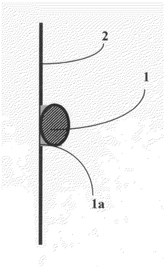
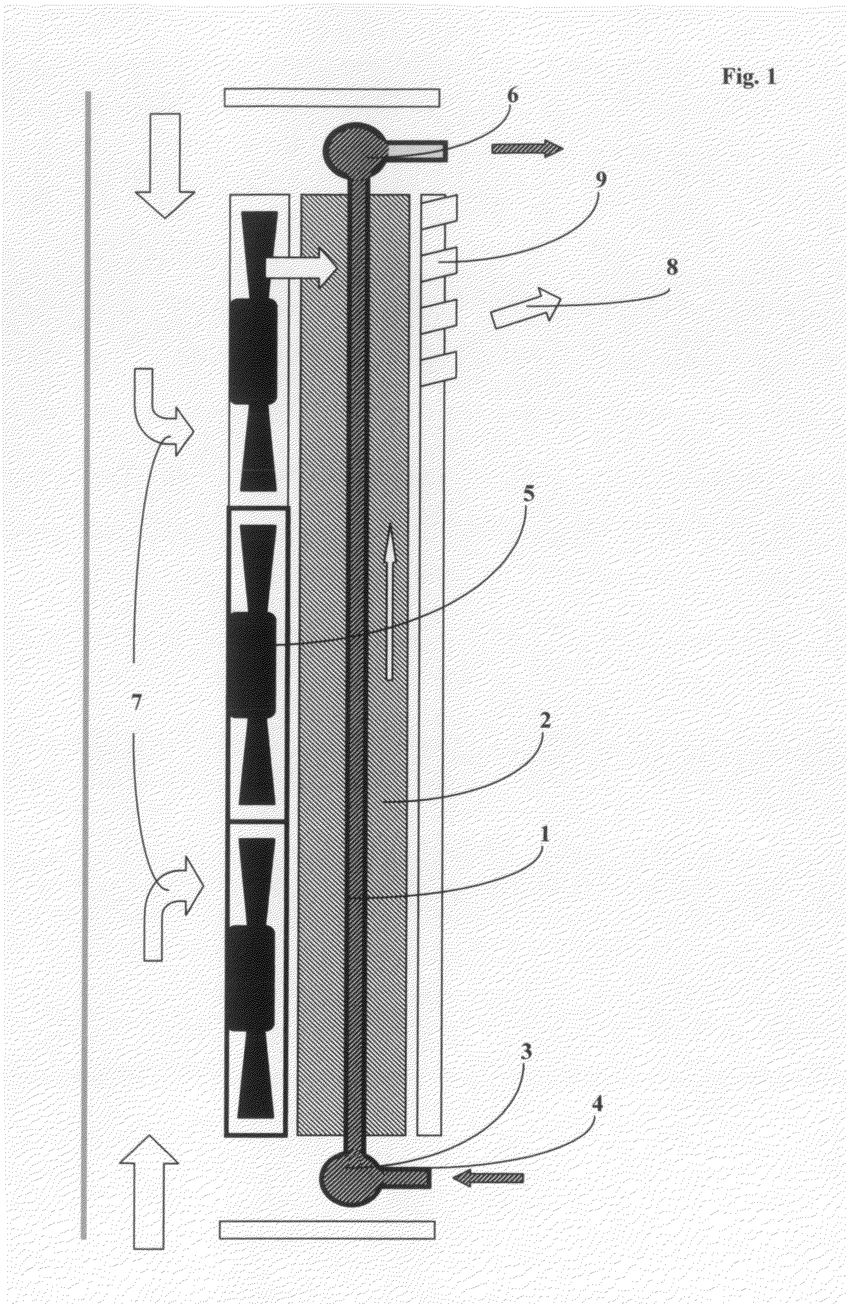
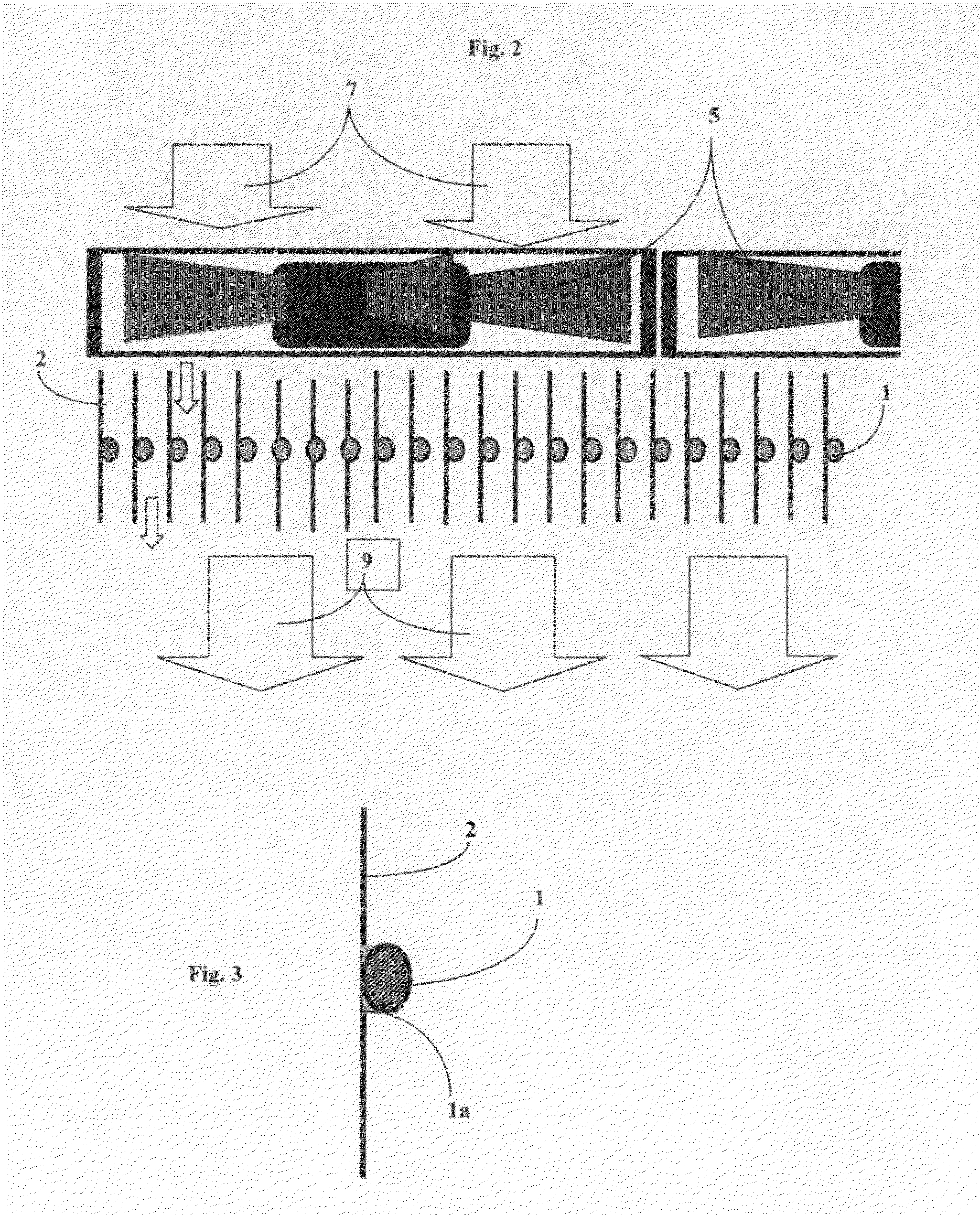
[0068]As described above, the present invention provides an apparatus and methods for fluid and heat exchange in the application of air conditioning of rooms and spaces in structures or dwellings. More particularly, the apparatus distributes small amount of conditioned (hot or cold) fluid into large number of small tubes each attached lengthwise with thin metal fins and oriented in the same direction FIG. 1, FIG. 2, FIG. 3 and FIG. 4; 1, 2 (47 tubes in a square ...


PUM


Abstract

A secondary refrigerant fluid is cooled or heated in the operation of a multiple Tube-fins heat exchanger arranged in parallel for fins to conduct heat transfer with air being propelled by a multi-row bank of low profile brushless fans. Fluid is controlled to ascend the bank of tubes in unison rate for high efficiency heat transfer with air. Large temperature differential exists between air and fluid when conditioned fluid travels through the tubes for a relatively short distance. A system of components is so arranged that the fluid flow rate to every heat exchanger is preset and the “on” or “off” operation of any heat exchanger does not affect the flow rate destined for other heat exchangers. Fluid is not transported to a heat exchanger when it is not in operation saving energy. Each heat exchanger is controlled by an integrated thermostat so occupants can set the air conditioning operation individually independent of all other heat exchangers.

Description

BACKGROUND OF INVENTION[0001]The present invention relates to an apparatus and methods that conduct controllable heat exchange between introduced air and very small amount of cold or hot conditioned fluid.[0002]Heat exchanger technology has long existed with two basic heat transfer mechanisms. In one of the most common applications a single long tube is bent back and forth with scores of thin heat conductive fins in layers attached perpendicularly on the folded long tube. In an attempt to increase heat conduction, an aluminum fin is used with punched holes and tiny collars swaged onto the coursing tube perpendicularly. Air is blown through the fin layers effecting heat transfer between air and liquid inside the tubing. Tubing contacts with the fins are small because the tube being inserted perpendicularly to the fin with small temperature contact area is characteristic of this practice. Purpose of this design is obvious in allowing as much heat transfer possible as fluid courses thr...

Claims


Application Information

Patent Timeline
Patent Type & Authority Applications(United States)
IPC IPC(8): F24F3/00F28F1/18F28F7/00F24F13/30F24F1/0073
CPCF24F1/0007F24F1/0033F28F1/20F28D1/05316F24F13/30F24F1/0073
Inventor PUN, JOHN YENKAI
Owner PUN JOHN YENKAI
Why Eureka
Try Eureka