Manufacturing method of heat flux sensor and heat flow generation device for use in the manufacturing method

a manufacturing method and heat flux sensor technology, applied in the direction of heat measurement, instruments, optical radiation measurement, etc., can solve the problem that the inspection process cannot be precisely carried out, and achieve the effect of short time, short time, and stable in a short tim

Active Publication Date: 2018-05-24
DENSO CORP
View PDF5 Cites 3 Cited by
  • Summary
  • Abstract
  • Description
  • Claims
  • Application Information

AI Technical Summary

Benefits of technology

[0013]According to the foregoing configuration, in the inspection process of the manufacturing method, the temperature of the heater plate can be controlled (temperature stabilization control can be performed) so that the heater plate is kept at the ambient temperature. Therefore, according to the manufacturing method of the present disclosure, in the case where the temperature of the heater plate needs to be stabilized in such a manner that the heater plate is heated to a temperature different from the ambient temperature, for example, the temperature can be stabilized in a short time. That is, according to the foregoing configuration, in the inspection process of the manufacturing method, even with some increase in the temperature of the heater plate, the temperature stabilization control can be performed with reference to the ambient temperature (a minor temperature change is enough). Accordingly, by the manufacturing method of the present disclosure, the temperature can be stabilized in a short time as compared to the case in which the heater plate is to be stabilized at a high temperature different from the ambient temperature. Therefore, according to the manufacturing method of the present disclosure, the inspection process of the heat flux sensor can be carried out in a short time.
[0014]The heater plate of the present disclosure is made in a film form. This reduces the heat capacity of the heater plate, to shorten the time taken for stabilizing the temperature according to the manufacturing method of the present disclosure. In addition, the heater plate is thin and heat leakage from the outer edge of the heater plate can be ignored.

Problems solved by technology

As a result, the relationship between the heat flow generated by the heating bodies J1 and the output voltage from the heat flux sensor J3 does not meet the desired relationship and the inspection process cannot be carried out precisely.

Method used


Image

  • Manufacturing method of heat flux sensor and heat flow generation device for use in the manufacturing method
  • Manufacturing method of heat flux sensor and heat flow generation device for use in the manufacturing method
  • Manufacturing method of heat flux sensor and heat flow generation device for use in the manufacturing method

Examples


first embodiment

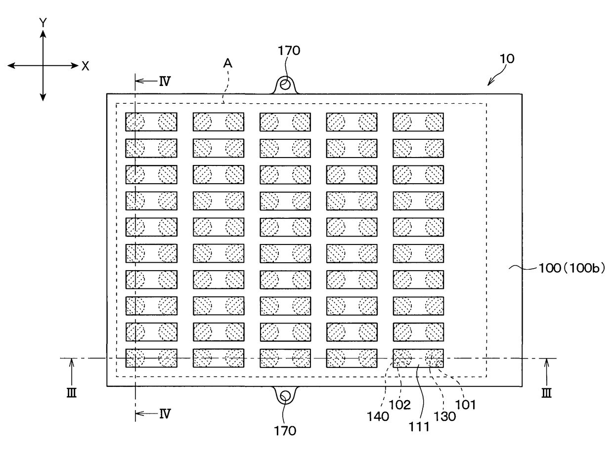
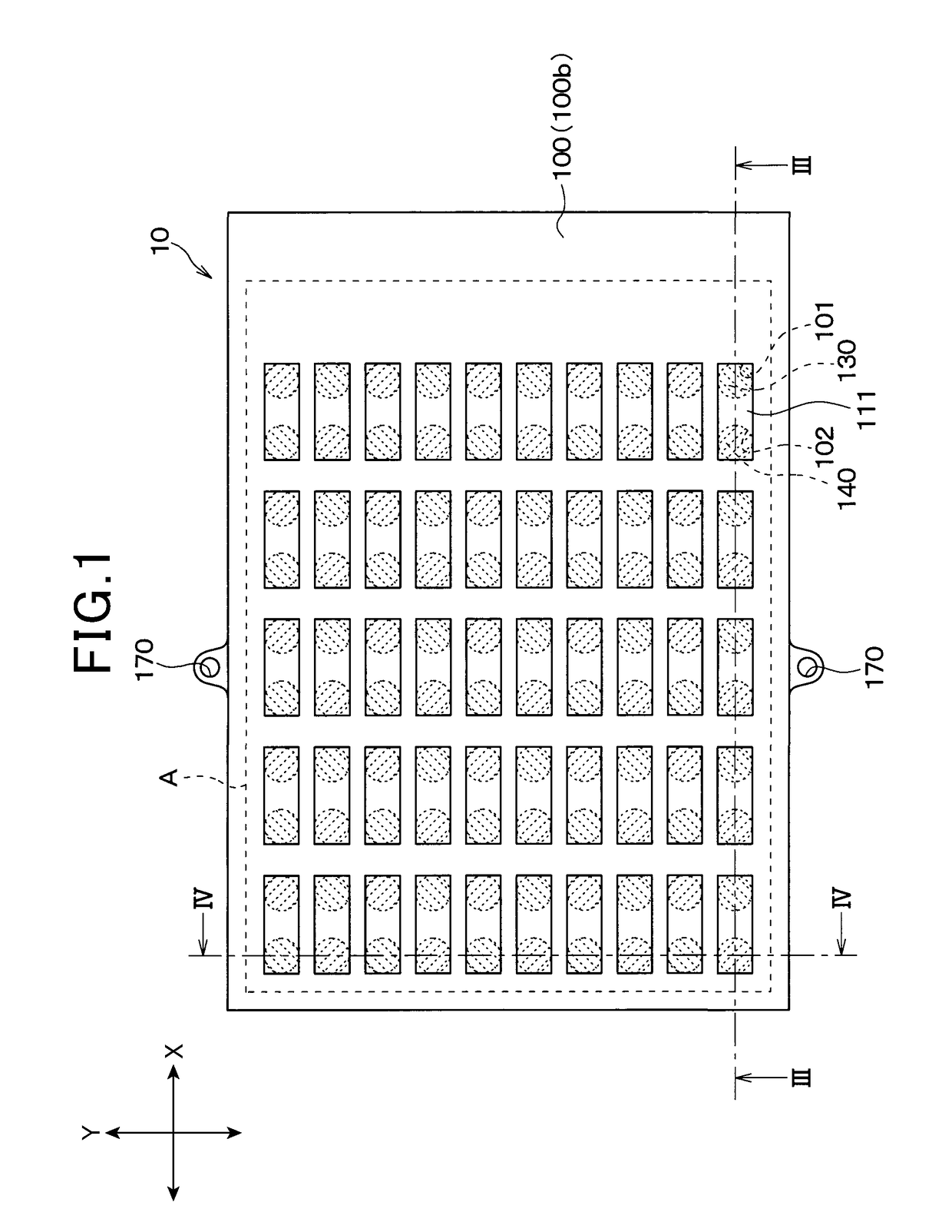
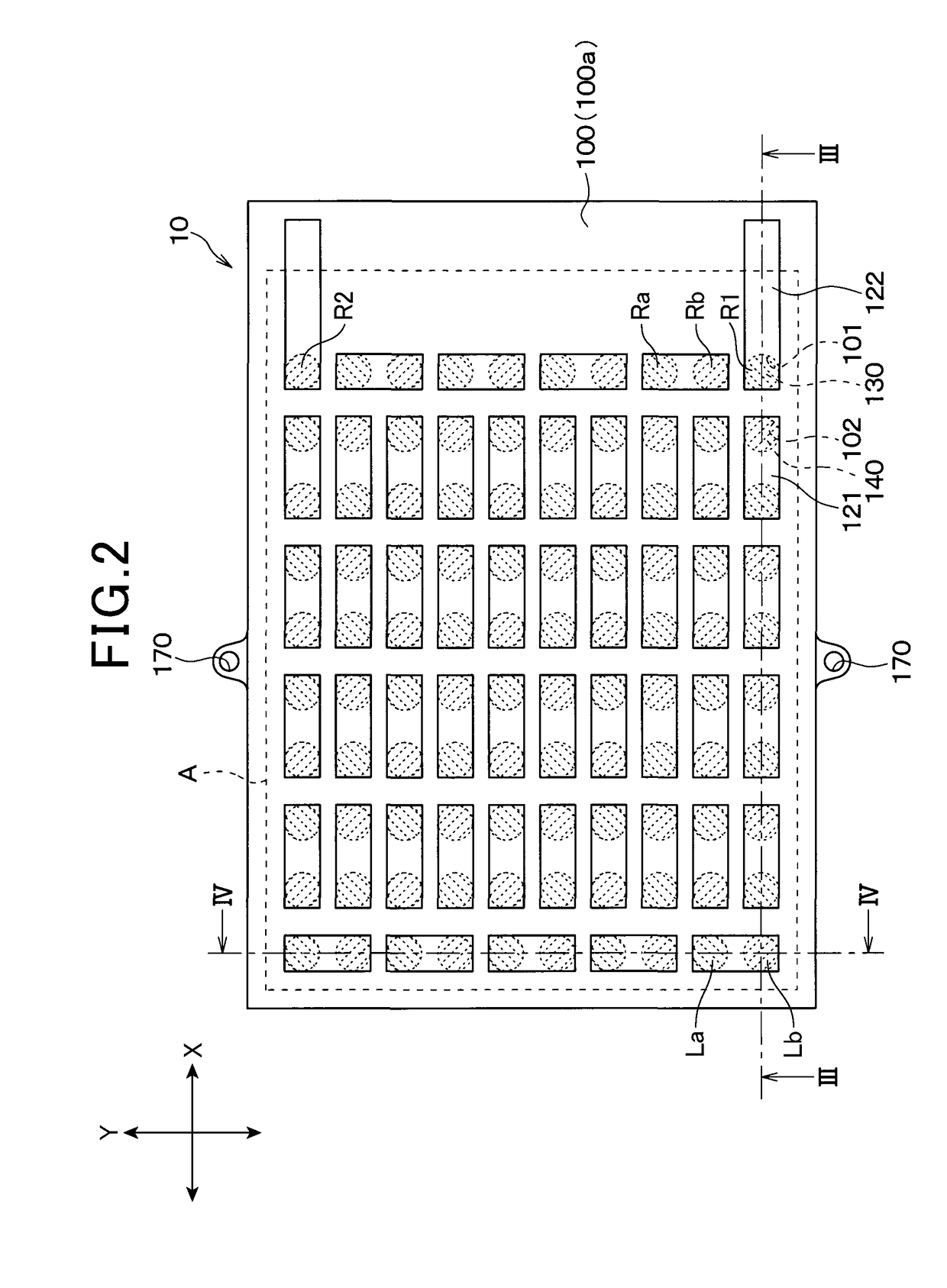
[0036]A first embodiment of the present disclosure will be described. Specifically, a configuration of a heat flux sensor manufactured by a manufacturing method according to an embodiment of the present disclosure and a configuration of a heat flow generation device for use in an inspection process of the manufacturing method will be described with reference to the drawings. First, a structure of the heat flux sensor according to the first embodiment will be described with reference to FIGS. 1 to 4.

[0037]A heat flux sensor 10 detects and outputs a heat flux as a heat flow crossing a unit area per unit time. The heat flux sensor 10 is formed of a thermoelectric element that outputs a heat flux as a voltage, for example, and generates an output voltage according to the heat flux. In the first embodiment, the heat flux sensor 10 is made in a film form. As illustrated in FIGS. 1 to 4, the heat flux sensor 10 is formed by integrating an insulation base material 100, a back surface protec...

second embodiment

[0101]A second embodiment of the present disclosure will be described. The second embodiment is different from the first embodiment in the configuration of the heat flux sensor. Accordingly, in the following description, only the differences from the first embodiment will be discussed.

[0102]In the first embodiment, the heat flux sensor 10 is formed of one thermoelectric element in which the first and second interlayer connection members 130 and 140 are connected in series as an example. Meanwhile, in the second embodiment, the heat flux sensor 10 includes a plurality of thermoelectric elements. Specifically, as illustrated by chain lines in FIG. 13, in a plurality of defined areas B1 to B6, the first and second interlayer connection members 130 and 140 are connected in series to form the separate thermoelectric elements in the individual areas. Each of the thermoelectric elements in the areas B1 to B6 has two connection patterns 122. Accordingly, the thermoelectric elements in the a...

third embodiment

[0105]A third embodiment of the present disclosure will be described. The third embodiment is different from the second embodiment in the configuration of the heater plate and the inspection process of the heat flux sensor. In the other respects, the third embodiment is the same as the second embodiment. In the following description, only the differences from the second embodiment will be discussed.

[0106]The heat radiation measurement plate 205 according to the third embodiment is configured in the same manner as the heat flux sensor 10 including a plurality of thermoelectric elements. In the third embodiment, the thus configured heat radiation measurement plate 205 is used to detect the rate of leaked heat flow in each area of the heat flux sensor 10. Specifically, as illustrated in FIG. 15, the rate of leaked heat flow can be measured in the inspection process of areas C1 to C6 of the heat flux sensor 10. In the third embodiment, the rates of heat flows generated in the areas C1 t...


PUM

PropertyMeasurementUnit
path widthaaaaaaaaaa
path lengthaaaaaaaaaa
resistanceaaaaaaaaaa

Abstract

According to a manufacturing method of a heat flux sensor, the heat flux sensor is sandwiched between a heater plate and a cooling unit. The heater plate is disposed on the first surface of the heat flux sensor, and the cooling unit is disposed on the second surface of the same. A heat radiation measurement plate is disposed on a surface of the heater plate opposite to the surface on which the heat flux sensor is disposed. According to this configuration, the temperature of the heater plate is controlled in an inspection process such that the heater plate is kept at an ambient temperature. This makes it possible to stabilize the temperature of the heater plate in a short time.

Description

TECHNICAL FIELD[0001]The present disclosure relates to a manufacturing method of a heat flux sensor (heat flow sensor) for use in detection of heat flux and a heat flow generation device for use in the manufacturing method.BACKGROUND ART[0002]In the conventional inspection process of a heat flux sensor, a predetermined heat flow is applied to the heat flux sensor and a sensor output is measured, and the heat flux sensor is evaluated for characteristics based on the measurement results. Specifically, the inspection process is carried out based on whether the relationship between the rate of heat flow generated by the application of a predetermined heat flow and the sensor output (for example, output voltage) meets a desired relationship. The method for the characteristic evaluation will be described with reference to FIG. 19.[0003]As illustrated in FIG. 19, according to the conventional method, a rectangular block surrounded by an electrothermal material J2 with favorable thermal con...

Claims


Application Information

Patent Timeline
Patent Type & Authority Applications(United States)
IPC IPC(8): G01K17/20G01J5/12G01J5/02G01K19/00
CPCG01K17/20G01J5/12G01J5/0205G01K19/00G01N25/18G01K17/00G01K17/06
Inventor GOUKO, NORIOSAKAIDA, ATUSIOKAMOTO, KEIJISHIRAISHI, YOSHIHIKO
Owner DENSO CORP
Why Eureka
Try Eureka