Dynamic layout method of power environment monitoring system

A dynamic environment monitoring and dynamic configuration technology, applied in transmission monitoring, transmission systems, electrical components, etc., can solve problems such as inability to adapt to smooth system upgrades, system hidden dangers, omissions, etc., to save manual configuration operation time and reduce manual intervention. degree, the effect of reducing the probability of misconfiguration

Inactive Publication Date: 2004-10-20
ZTE CORP
View PDF0 Cites 7 Cited by
  • Summary
  • Abstract
  • Description
  • Claims
  • Application Information

AI Technical Summary

Problems solved by technology

[0008] With the continuous upgrade of the system version or the constant change of the data structure used, in the process of upgrading the old system, it is often necessary to reconfigure the monitoring objects or modify the content of the data structure according to the changes of the new system. If these tasks require manual It is inevitable that there will be omissions during the system upgrade process, which will bring many hidden dangers to the upgraded system and cannot meet the needs of smooth system upgrades.
[0009] In view of the shortcomings of using the existing static and manual methods for configuration in the current centralized monitoring system, the present invention proposes a dynamically configurable dynamic environment monitoring system and its method that realize automatic, fast and accurate configuration management of monitored objects

Method used


Image

  • Dynamic layout method of power environment monitoring system
  • Dynamic layout method of power environment monitoring system
  • Dynamic layout method of power environment monitoring system

Examples


Embodiment Construction

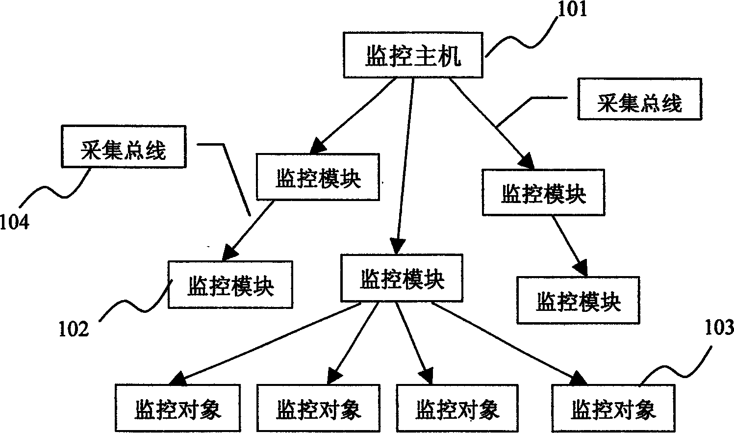
[0023] Such as figure 1 As shown, it is a schematic diagram of the topology relationship of the centralized monitoring system (system for short) of the present invention, which includes a monitoring host 101, a monitoring module 102, a monitoring object 103 and an acquisition bus 104 for data collection between each other; wherein the monitoring host can manage multiple Each monitoring module can manage multiple monitoring objects. The relationship between the above components is described as follows:

[0024] Monitoring object 102, which is the smallest management unit in the system, corresponds to each monitored analog and digital quantity for the power environment centralized monitoring system in the communication field;

[0025] The monitoring module 103 is a collection of monitoring objects and also the smallest data collection unit in the system. The system completes the data collection of all the monitoring objects under it by scanning the data of each monitoring module...


PUM


Abstract

The method of dynamic configuration of power environment monitor system includes setting unique id and related properties for monitored object corresponding to a monitored point; set-up unified physical communication interface between monitoring module and system; set-up unified interface protocol between monitoring module and system; realizing automatic recognizing monitoring module and automatic configuring monitored object by system. The method lowers degree of manual intervention in operating, raises configuration and management efficiency and reduces umstabilizing factor brought by manual operation and error configuration, and save time.

Description

technical field [0001] The invention relates to a centralized monitoring system, in particular to a dynamic configuration method of a power environment monitoring system in the communication field. Background technique [0002] In the centralized monitoring system (such as the power environment monitoring system in the communication field), the smallest management unit is the monitoring object. At present, the configuration management of monitoring objects is mostly carried out manually, and its shortcomings are obvious in the following three situations: [0003] 1. When the relationship between monitoring objects in the system is complex [0004] The basic steps to configure the monitoring objects in the system are: first, configure the acquisition bus for the monitoring objects, add the corresponding monitoring module on the acquisition bus, and then add the monitoring objects that need to be configured in the monitoring module. This process is mor...

Claims


Application Information

Patent Timeline
Patent Type & Authority Applications(China)
IPC IPC(8): H04B17/00
Inventor 张雪林陈百利胡杨
Owner ZTE CORP
Why Eureka
Try Eureka