Automatic material feeding device

An automatic feeding and trough technology, applied in loading/unloading, transportation and packaging, conveyors, etc., can solve problems affecting the efficiency of cylindrical cells entering the shell, disordered arrangement of aluminum shells, and inaccurate positioning of aluminum shells, etc., to achieve Reduce the degree of manual intervention, reduce damage, and improve production efficiency

Active Publication Date: 2019-01-11
HEFEI GUOXUAN HIGH TECH POWER ENERGY
View PDF17 Cites 4 Cited by
  • Summary
  • Abstract
  • Description
  • Claims
  • Application Information

AI Technical Summary

Problems solved by technology

[0003] There is a common defect in the above two methods: since the aluminum shell is a cylinder, it is easy to roll, and if you want to stack or arrange it neatly, it will take a lot of energy; When positioning, the arrangement of the aluminum shells will be disordered due to jitter, which will not only cause inaccurate positioning of the aluminum shells, but also affect the efficiency of the subsequent cylindrical cells into the shell

Method used


Image

  • Automatic material feeding device
  • Automatic material feeding device
  • Automatic material feeding device

Examples


Embodiment Construction

[0047] The present invention will be further described below in conjunction with accompanying drawing:

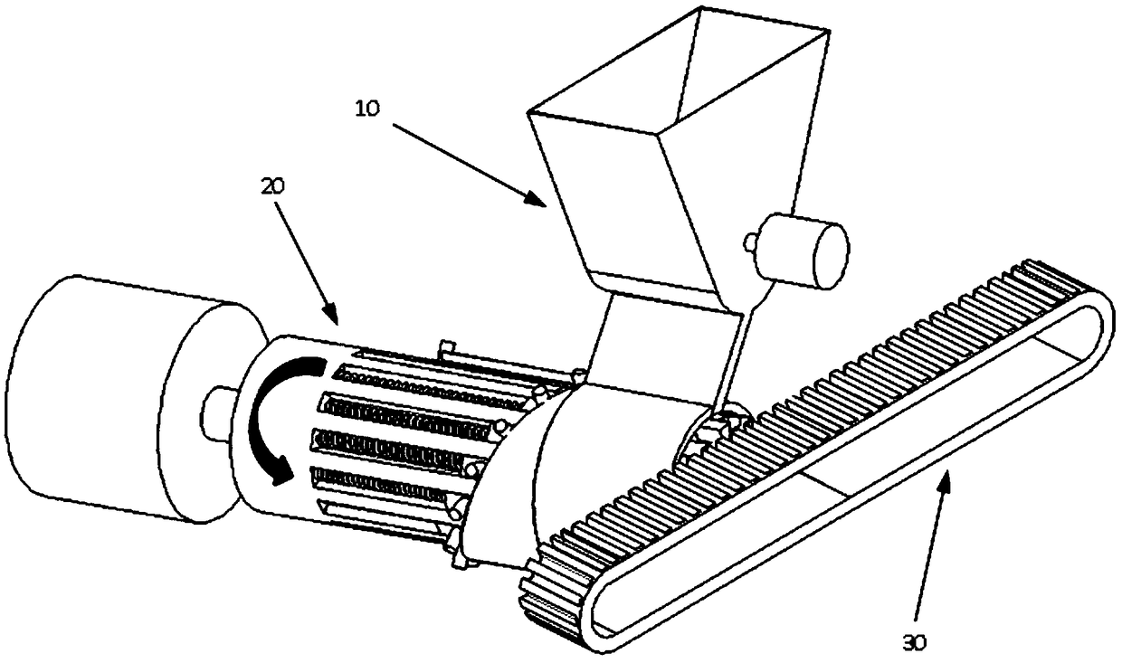
[0048] Such as figure 1 As shown, an automatic feeding device includes a feeding mechanism 10 and a propulsion mechanism 20;

[0049] Such as Figure 6As shown, the propulsion mechanism 20 includes a rotating wheel 201, and the outer wall of the rotating wheel 201 is provided with feeding grooves 2011 at equal intervals in the axial direction, and a push block 2013 is movable in the feeding groove 2011. The inner end of the block 2013 is connected to the inner wall of the feeding chute 2011 through an elastic member, and a stop post 2014 is installed on the push block 2013 at one end of the elastic member;

[0050] In a further solution, the blocking column 2014 is movably installed on the push block 2013 and rotates around its own central axis. When the helix of the spiral cover rotates tangentially to the retaining post, the retaining post can rotate freely, avoiding t...


PUM


Abstract

The invention relates to an automatic material feeding device. The automatic material feeding device comprises a material inlet mechanism and a pushing advancing mechanism, wherein the pushing advancing mechanism comprises a rotating wheel, the outer wall of the rotating wheel is axially and equidistantly provided with material inlet grooves, the material inlet grooves are internally and movably provided with pushing blocks in a clamped manner, the inner ends of the pushing blocks are connected with the inner walls of the corresponding material inlet grooves through elastic parts, and the parts, at one ends of the corresponding elastic parts, of the pushing blocks are provided with blocking columns; and the material inlet mechanism comprises a material inlet hopper and a connection barrel,the bottom end of the material inlet hopper is connected with the side wall of the connection barrel through a material discharging hopper and communicates with the inner cavity of the connection barrel, one side of the connection barrel is fixedly connected with a spiral hood with the outer end face being in a spiral shape, the connection barrel and the spiral hood are arranged on the part, at one ends of the pushing blocks, of the rotating wheel together in a sleeving manner, and the spiral outer end face of the spiral hood is tangent to the blocking columns. By means of the automatic material feeding device, arranging performed on messy materials can be realized, force storing and releasing of the pushing blocks are realized through rotation of the pushing advancing mechanism, aluminumshells arranged neatly are pushed and fed to a material feeding station, the labor is lightened, and the production efficiency is improved.

Description

technical field [0001] The invention relates to a mechanical device, in particular to an automatic feeding device for a cylindrical aluminum case of a lithium battery. Background technique [0002] The production process of lithium-ion cylindrical batteries involves the feeding process of cylindrical aluminum shells. There are two main feeding methods at present: one is to stack the cylindrical aluminum shells neatly in multiple layers in the material box, and then send the material boxes to the material loading workers. The second is that there are several grooves in a tray for placing aluminum shells, and only one layer of aluminum shells is placed on each tray, and then the trays are stacked and sent to the loading station. [0003] There is a common defect in the above two methods: since the aluminum shell is a cylinder, it is easy to roll, and if you want to stack or arrange it neatly, it will take a lot of energy; When positioning, the order of the aluminum shells wil...

Claims


Application Information

Patent Timeline
Patent Type & Authority Applications(China)
IPC IPC(8): B65G65/48B65G47/26B65G47/82
CPCB65G47/26B65G47/82B65G65/4881B65G2201/0214
Inventor 高冲程辉王晨旭
Owner HEFEI GUOXUAN HIGH TECH POWER ENERGY
Why Eureka
Try Eureka