Disinfestation light capable of clering away insects automatically

An insect-killing lamp and automatic cleaning technology, which is applied to the field of insect-killing equipment using spectral insect traps, can solve the problems of low insect-killing efficiency, labor-intensive, affecting the high-pressure killing effect, etc., so as to save manpower and improve insecticidal efficiency. Effect

Inactive Publication Date: 2004-10-27
徐昌春
View PDF2 Cites 15 Cited by
  • Summary
  • Abstract
  • Description
  • Claims
  • Application Information

AI Technical Summary

Problems solved by technology

The efficiency of pest control is not high, and it takes a lot of manpower
However, after repeated cleaning, t

Method used


Image

  • Disinfestation light capable of clering away insects automatically
  • Disinfestation light capable of clering away insects automatically
  • Disinfestation light capable of clering away insects automatically

Examples


Embodiment Construction

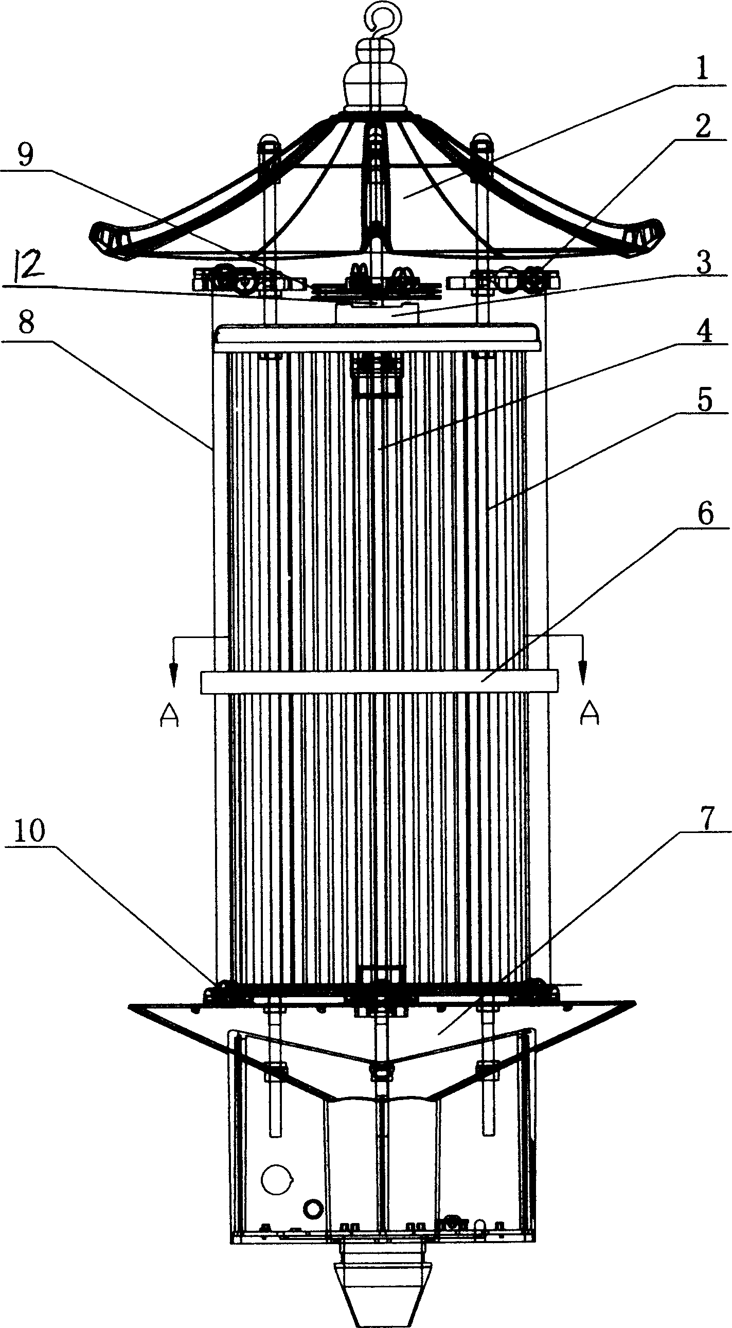
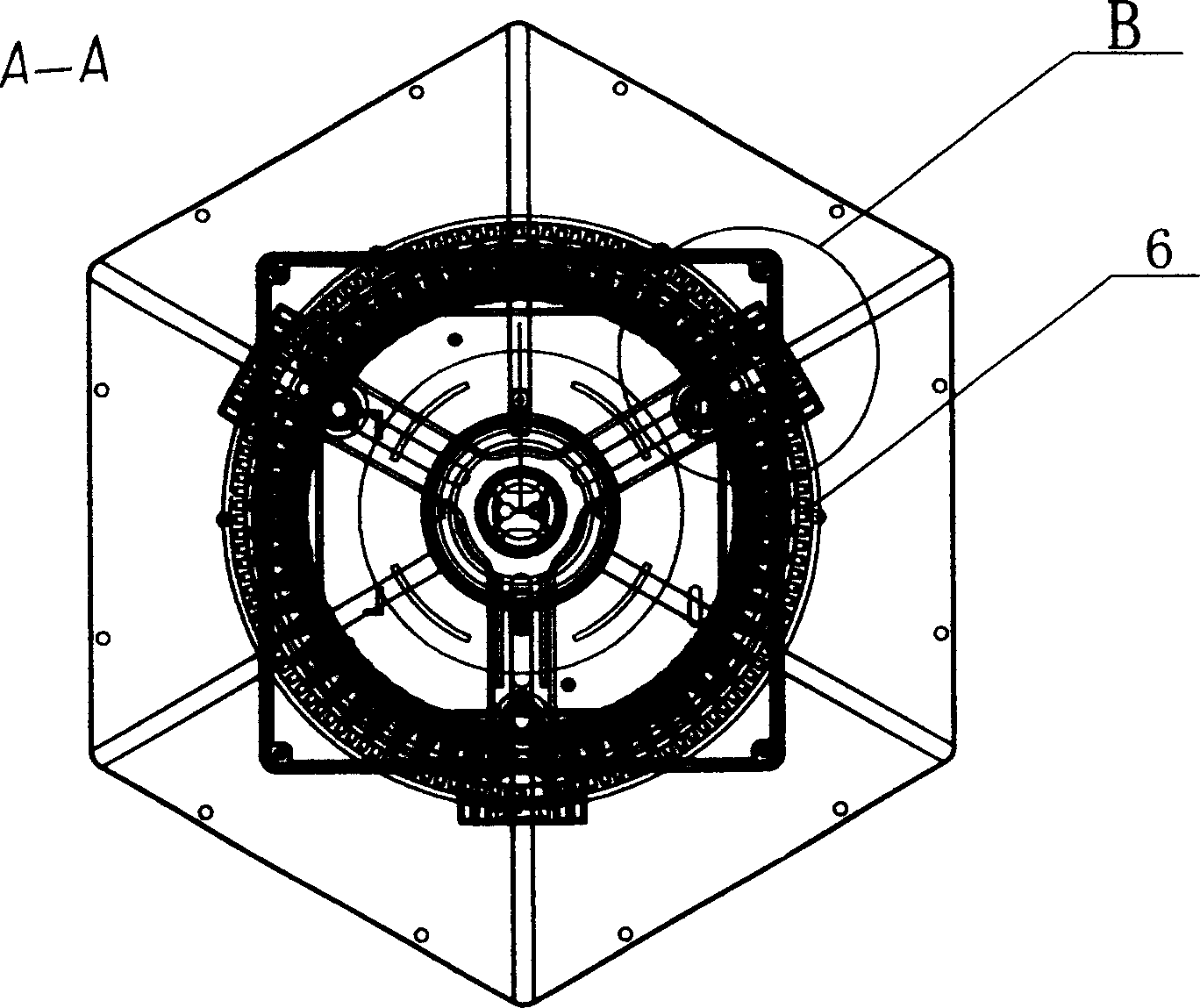
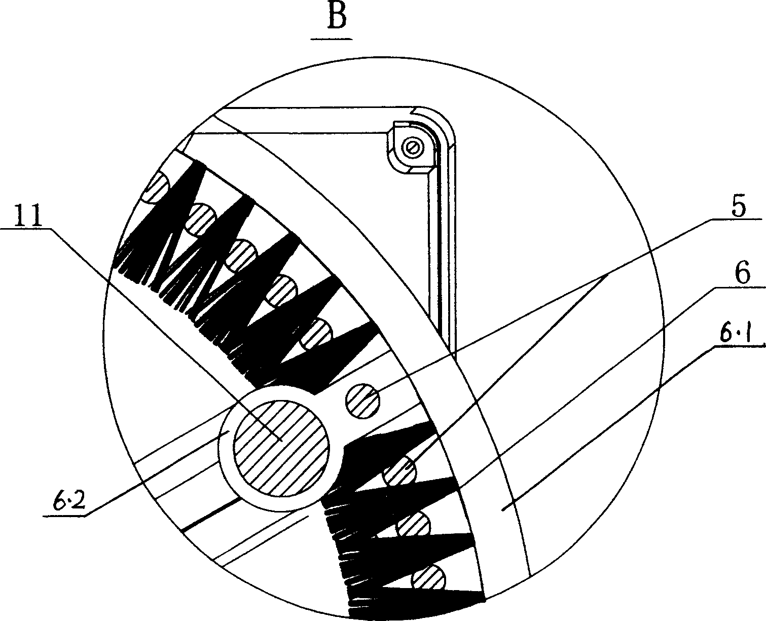
[0009] Lamp tube 4 is installed vertically under the lamp cap 1, and there is a cylindrical high-voltage grid 5 with positive and negative high-voltage lines arranged in sequence around the lamp tube 4, and a ring-shaped brush 6 is installed on the outside of the grid, and the bristles on the brush holder 6.1 stick to each high-voltage wire inward . Both the high voltage grid 5 and the lamp tube 4 are installed between the upper end of the bracket and the base 7 . The two ends of stay cord 8 are fixed on the hairbrush 6 respectively. There are 3 upper and lower pulleys 2 and 10 respectively, which are distributed in an equilateral triangle, and each corresponding pulley up and down constitutes a pulley block respectively.

[0010] Three guide pillars 11 parallel to the high-voltage wires are arranged in the cylindrical high-voltage grid 5, and each guide pillar cover 6.2 protruding laterally from the inner wall of the annular brush holder 6.1 is matched with each guide pillar...


PUM


Abstract

An insect killing lamp able to automatically remove the dead insects is composed of lamp cap, attracting lamp tube under lamp cap, a high-voltage grate surrounding said lamp tube and composed of positive and negative high-voltage lines arranged sequentially, an insect collector under the lamp tube, and brush close to said high-voltage grate and driven by motor controlled by time chip for timely removing the dead insects from said high-voltage grate.

Description

Technical field: [0001] The invention relates to an extermination device, in particular to an extermination device using a spectrum to attract insects, such as an extermination lamp and the like. Background technique: [0002] In the past, insect killer lamps, as introduced in Chinese patents 93235977.9 and 96227245.0, have electric grids outside the insect trap lamps, which can effectively kill phototaxis pests in all directions. These insect killer lamps will have problems in fields and other places where there are many pests. When the killed pests adhere to the grid and gather too much, they will block the light of the insect trap lamp, thus losing the purpose of attracting pests. At this time, it is necessary to manually remove the pests attached to the grid, sometimes several times a night. The efficiency of disinsection is not high, and it takes a lot of manpower. However, after repeated removal, the mucus layer on the wire will become an insulating layer, affecting ...

Claims


Application Information

Patent Timeline
IPC IPC(8): A01M1/04A01M1/22
Inventor 徐昌春
Owner 徐昌春
Why Eureka
Try Eureka