Back reflector and back projecting picture displaying appts. using same

A technology of rear projection and image display, applied in projection devices, projectors with built-in/external screens, mirrors, etc., can solve the problems of reduced light quantity, color shift or deterioration of brightness performance, etc., to improve the surface smoothness , the effect of suppressing color shift or brightness deterioration, and improving contrast performance

Inactive Publication Date: 2004-10-27
HITACHI LTD
View PDF3 Cites 2 Cited by
  • Summary
  • Abstract
  • Description
  • Claims
  • Application Information

AI Technical Summary

Problems solved by technology

Therefore, in the image light of the projected image projected on the screen, the amount of light in the wavelength region of the trough (a) of the ripple decreases, causing color shift and deterioration of luminance performance.

Method used


Image

  • Back reflector and back projecting picture displaying appts. using same
  • Back reflector and back projecting picture displaying appts. using same
  • Back reflector and back projecting picture displaying appts. using same

Examples


Embodiment Construction

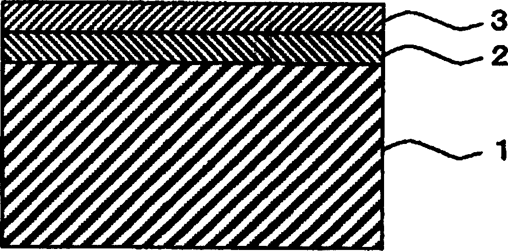
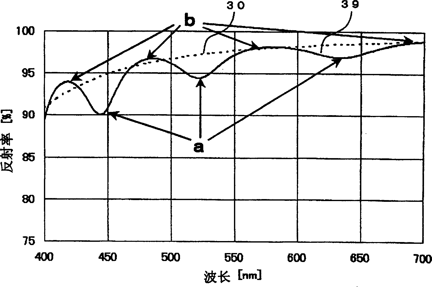
[0032] Next, embodiments of the present invention will be described with reference to the drawings. The present invention is characterized in that a single-layer overcoat layer of a colorless and transparent resin is formed as a protective film on a reflective film provided on a base material for a rear reflector used in a rear projection type image display device. In addition, the film thickness of the overcoat layer is set to a thin film below 1 μm to obtain substantially the same contrast performance and resolution performance as those of ordinary glass mirrors. In addition, it is characterized in that the film thickness of the above-mentioned overcoat layer is formed to such a thickness that the wavelength of the peak of the wave due to interference due to thinning is different from the projection image light projected from the projection device or the light source built in the projection device. The wavelengths of the green bright lines are approximately equal.

[0033] ...


PUM


Abstract

In the present invention, there is disclosed a reflective mirror whose contrast or resolution performance is equal to that of a surface mirror of a glass mirror for general use and which does not have any problem in reliability of resistance to environment and whose color shift or brightness performance is inhibited from being degraded. For this, in the present invention, a reflective film is formed on a glass substrate by use of silver mirror reaction, and a topcoat is formed of a colorless / transparent resin. At this time, a wavelength of a crest of a ripple indicated by a reflectance characteristic is constituted to substantially agree with that of a green luminescent line. Accordingly, a back projection type video display device which is satisfactory in the contrast or resolution performance can be prepared.

Description

technical field [0001] The present invention relates to a projection device for projecting an optical image corresponding to a video signal, a rear projection type video display device for projecting an optical image from the back side of a screen, and a rear mirror using the same. The rear reflector changes the optical path of the projected image light toward the screen. In the back reflection mirror of the present invention, a metal thin film is used to form its reflection surface, and a colorless and transparent resin is coated on the surface of the metal thin film for protection. Background technique [0002] Reflectors (hereinafter referred to as rear reflectors) that change the optical path of projected image light used in a rear projection type image display device that is projected onto a screen from the rear side toward the screen are known, for example, Reflecting mirror disclosed in Publication No. 2001-235798. That is, an aluminum (Al) reflective film is formed...

Claims


Application Information

Patent Timeline
Patent Type & Authority Applications(China)
IPC IPC(8): G02B1/10G02B5/08G02B5/26G02B27/18G03B21/10G03B21/28
CPCG02B5/08G02B5/26
Inventor 益冈信夫平田浩二安达启西村贞之岶尾惠小寺喜卫
Owner HITACHI LTD
Why Eureka
Try Eureka