Needle thread feeding device of sewing machine

A technology of exporting device and sewing machine, which is applied to sewing machine components, sewing machine thread take-up device, sewing equipment, etc., can solve the problems of oil leakage and dust, unfavorable operator safety, intrusion, etc., and achieve lightweight, prevent oil leakage and dust. The effect of intrusion into the sewing machine arm and shortening

Inactive Publication Date: 2010-09-22
YAMATO SEWING MASCH MFG CO LTD
View PDF7 Cites 0 Cited by
  • Summary
  • Abstract
  • Description
  • Claims
  • Application Information

AI Technical Summary

Problems solved by technology

[0004] However, in the above-mentioned conventional sewing machine with the needle thread lead-out device, in order to fix the needle thread passage, since at the upper wall portion, there is formed the upper end portion of the needle bar to extend upwards from the upper wall portion of the sewing machine arm front end. Therefore, not only the possibility of oil leakage and dust intrusion into the arm of the sewing machine will occur from the through hole, but also because the needle thread passage protruding upward performs high-speed up-and-down reciprocating motion, in terms of safety for operators, etc. It's not good to see
In addition, due to the lengthening of the needle bar, and the increase in the weight of the needle bar caused by the fixing of the needle thread channel, it will naturally hinder the high-speed sewing speed.

Method used


Image

  • Needle thread feeding device of sewing machine
  • Needle thread feeding device of sewing machine
  • Needle thread feeding device of sewing machine

Examples


Embodiment Construction

[0017] Embodiments of the present invention will be described below with reference to the drawings.

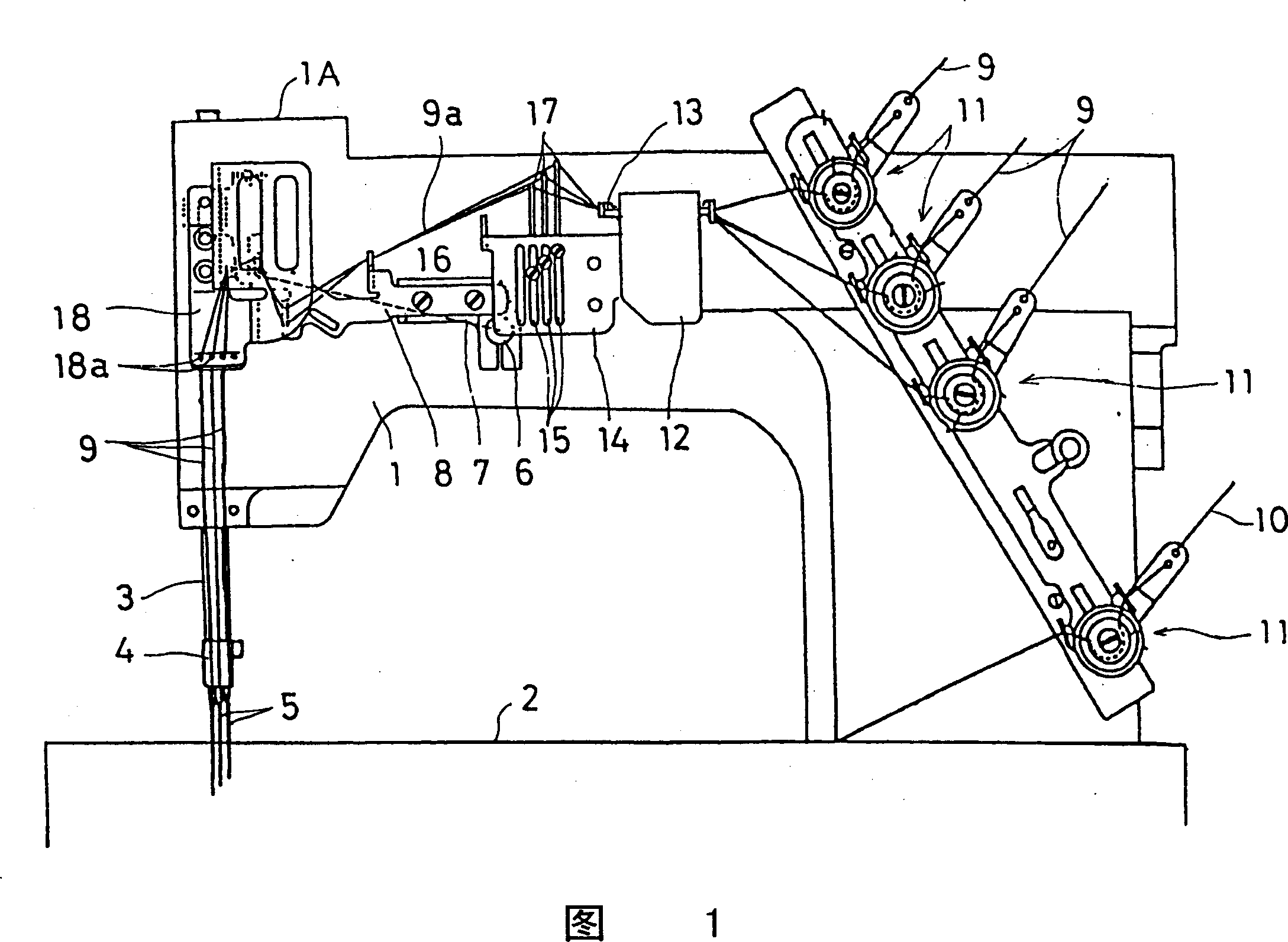
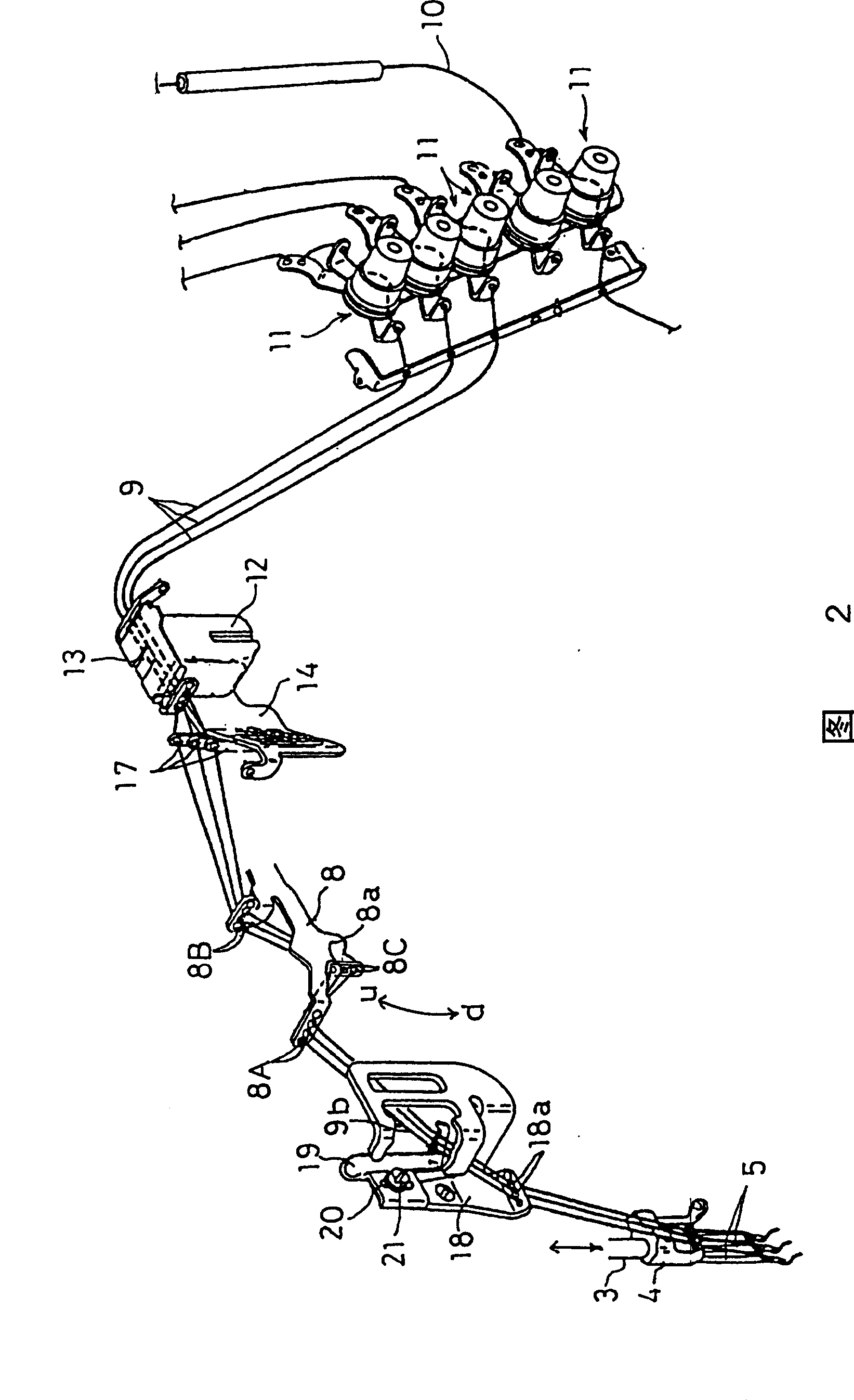
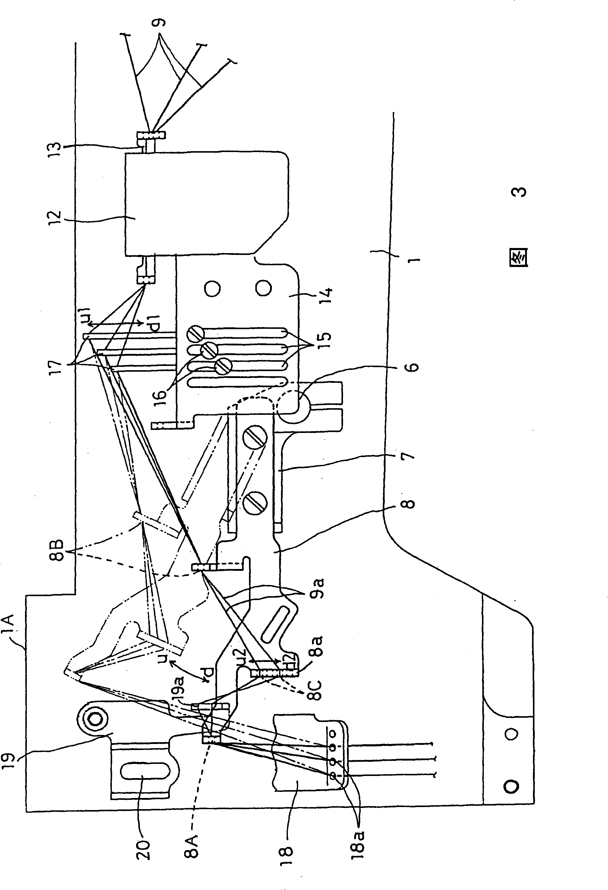
[0018] Figure 1 ~ Figure 3 Among them, 1 is the arm of the sewing machine, and 2 is the bottom plate of the sewing machine. The needle bar 3 is supported at the left end (front end) of the arm of the sewing machine 1, and the needle bar 3 is supported on the arm of the sewing machine by a known crank mechanism and insertion. The drive spindle (not shown) in 1 is interlocked and can reciprocate in the up and down direction, and at the needle bar 3, a blank pressing mechanism is adjacently provided (because it is known, so the detailed description is omitted).

[0019] At the lower end of the needle bar 3, three needles 5 are installed through the needle clamp 4. At the same time, the range of the up and down reciprocating movement of the needle bar 3 is set to: In this state, the upper end portion does not protrude upward from the upper wall portion 1A of the left end portion...


PUM


Abstract

To enable a superior sewing to be carried out without producing any poor sewing or reduction in quality of round-shaped raised portion or the like even in the case that a normal usual cloth is applied as an item to be sawn and a soft and expandable raw material cloth such as a micro-fiber cloth is applied. A movable needle thread feeding member 8 arranged at a sewing machine arm segment 1 so as to be reciprocated and oscillated in a vertical direction under a synchronous operation with a vertical reciprocating motion of a needle rod 3 and a needle 5, to cause a needle thread 9 passed through a specified needle thread path 13 and supplied to be descended and guided toward the needle 5 is provided with a needle thread guiding segment 8a having a third needle thread feeding hole 8C for feeding out and guiding a needle thread segment 9a between a first needle thread feeding hole 8A formed at its extremity end and a second needle thread feeding hole 8B formed at a substantial intermediate portion in a longitudinal direction under a state in which it is bent substantially in a V-shape in a downward direction. (C)2004,JPO .

Description

[0001] The present invention is a divisional application whose application number is 03130778.7, the application date is April 30, 2003, and the title of the invention is a needle thread deriving device for a sewing machine. technical field [0002] The present invention relates to a sewing machine with a needle thread lead-out device mainly suitable for multi-needle flat chain sewing machines, in particular to a sewing machine with a needle thread lead-out device having the following components: The needle bar that is supported on the front end of the arm of the sewing machine so that the driving spindle is interlocked and can reciprocate in the up and down direction; the needle installed at the lower end of the needle bar; including the looping and gray cloth feeding mechanism, accommodated in the bottom plate of the sewing machine The sewing member at the front end of the needle; the thread adjuster that adjusts the tension of the supply needle and the looping needle thread ...

Claims


Application Information

Patent Timeline
Patent Type & Authority Patents(China)
IPC IPC(8): D05B49/00D05B51/00
Inventor 岩井胜彦井上忠德草积要
Owner YAMATO SEWING MASCH MFG CO LTD
Why Eureka
Try Eureka