Needle thread feeding device of sewing machine

一种导出装置、缝纫机的技术,应用在缝纫机元件、缝纫机挑线装置、缝纫器械等方向,能够解决缝制速度的高速化防碍、作业者安全性不利、漏油尘埃等问题,达到实现短缩化、防止漏油及尘埃侵入缝纫机臂部内、实现轻量化的效果

Inactive Publication Date: 2010-12-22
YAMATO SEWING MASCH MFG CO LTD
View PDF1 Cites 0 Cited by
  • Summary
  • Abstract
  • Description
  • Claims
  • Application Information

AI Technical Summary

Problems solved by technology

[0004] However, in the above-mentioned conventional sewing machine with the needle thread lead-out device, in order to fix the needle thread passage, since at the upper wall portion, there is formed the upper end portion of the needle bar to extend upwards from the upper wall portion of the sewing machine arm front end. Therefore, not only the possibility of oil leakage and dust intrusion into the arm of the sewing machine will occur from the through hole, but also because the needle thread passage protruding upward performs high-speed up-and-down reciprocating motion, in terms of safety for operators, etc. It's not good to see
In addition, due to the lengthening of the needle bar, and the increase in the weight of the needle bar caused by the fixing of the needle thread channel, it will naturally hinder the high-speed sewing speed.

Method used


Image

  • Needle thread feeding device of sewing machine
  • Needle thread feeding device of sewing machine
  • Needle thread feeding device of sewing machine

Examples


Embodiment Construction

[0017] Hereinafter, embodiments of the present invention will be described with reference to the drawings.

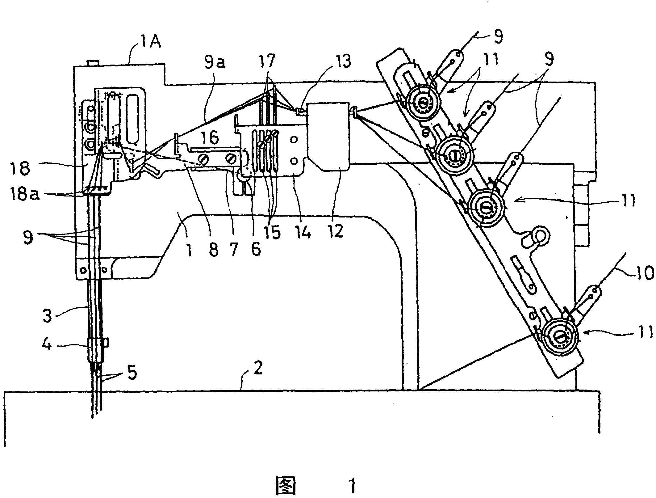
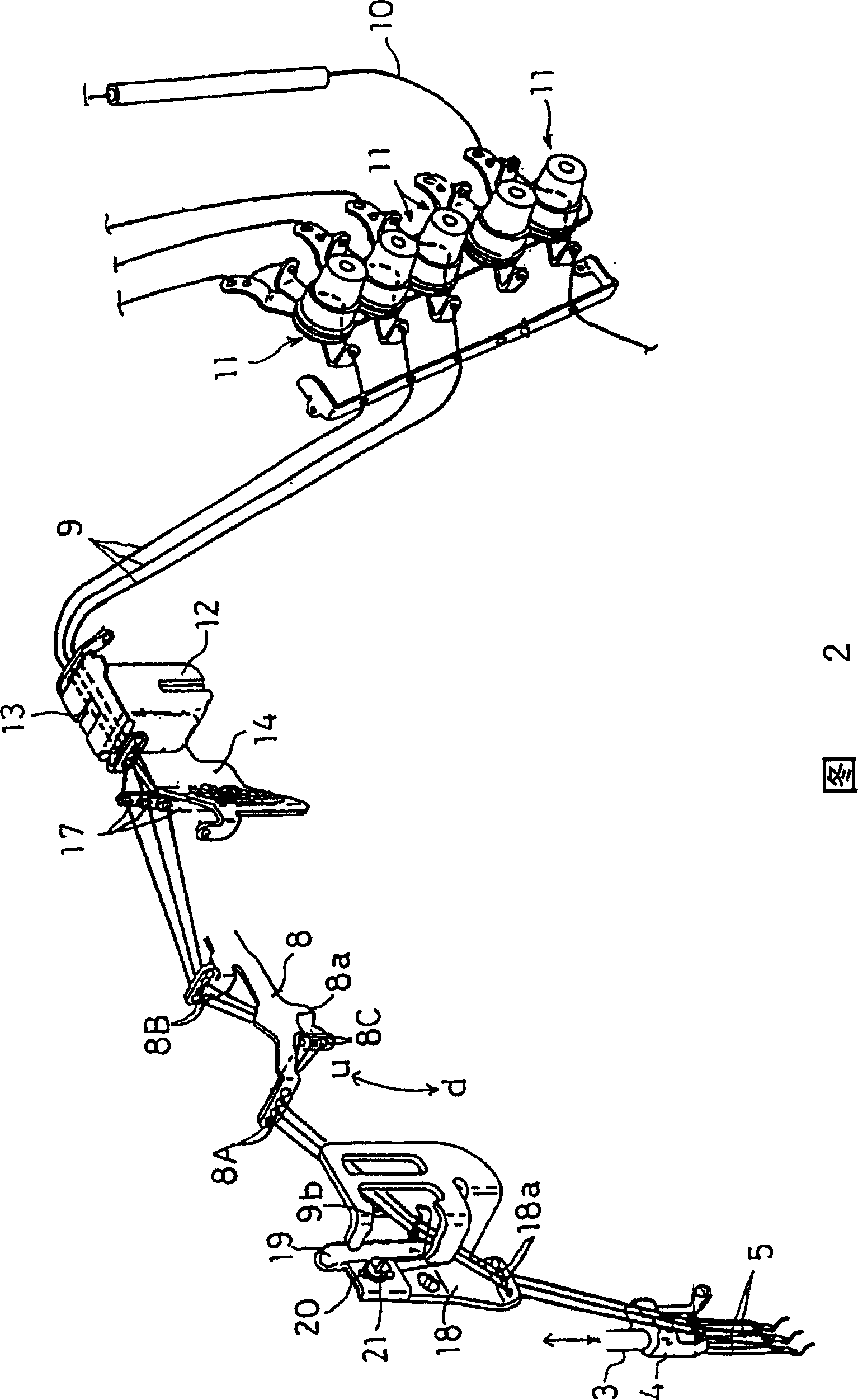
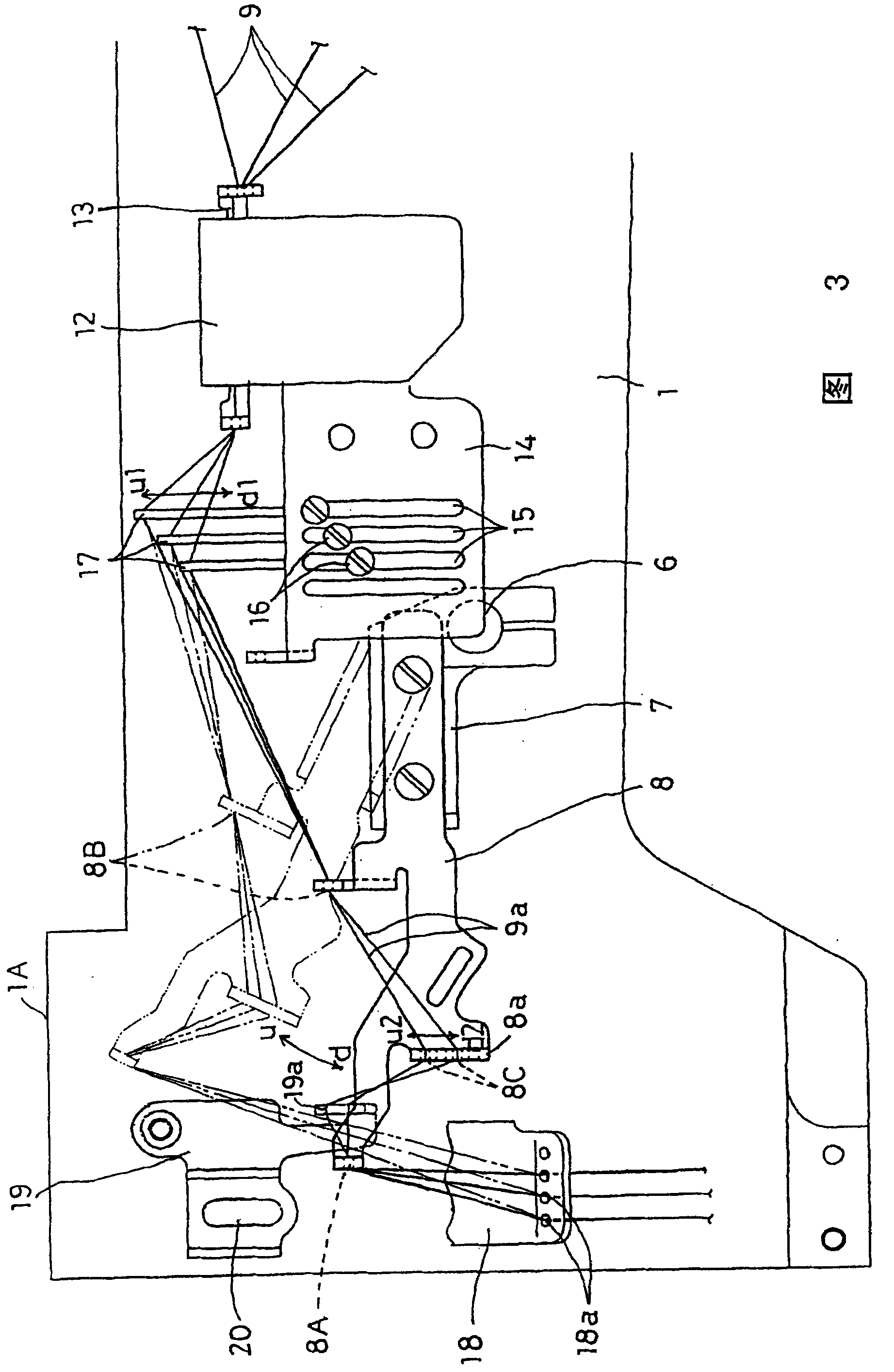
[0018] Figure 1 ~ Figure 3 Among them, 1 is the sewing machine arm, and 2 is the sewing machine bottom plate. A needle bar 3 is supported at the left end (front end) of the sewing machine arm 1. The needle bar 3 is supported by a well-known crank mechanism and inserted through the sewing machine arm. The drive spindle (not shown) in 1 is linked to reciprocate in the vertical direction, and the needle bar 3 is provided with a blank pressing mechanism adjacent to it (because it is well known, detailed description is omitted).

[0019] At the lower end of the needle bar 3, three needles 5 are installed through the needle clamp 4, and at the same time, the range of the up and down reciprocating movement of the needle bar 3 is set to: even when the needle bar 3 moves up to the top dead center In the state, the upper end does not extend upward from the upper wall portion 1A of t...


PUM


Abstract

A sewing machine which comprises a needlework leading out device is suitable for the flat-seam machine and the like, the needle stick (3) traverses the crank mechanism and is supported at the front end of the sewing machine arm part (1) while doing reciprocating motion in the up-and-down direction, and the up-and-down reciprocating motion range of the needle stick (3) is set that the upper end part of the needle stick (3) does not extend upwards from the upper wall part (1A) at the front end part of the sewing machine arm part (1) even the needle stick (3) ascends to the dead point. With thisstructure the needlework channel which synchronously does up-and-down motion with the needle stick can be eliminated from the upper end part of the needle stick, the sewing machine arm part can be basically realized with enclosing and the intrusion of leaked oil and dust can be prevented, and with the realization of shortening and lighting of the needle stick length the high speed of the sewing velocity can be easily adapted.

Description

[0001] The present invention is a divisional application with an application number of 03130778.7, an application date of April 30, 2003, and an invention title of "Sewing Machine Needle and Thread Lead-out Device". Technical field [0002] The present invention relates to a sewing machine with a needle thread lead-out device mainly suitable for a multi-needle flat chain sewing machine, and in particular to a sewing machine with a needle thread lead-out device having the following components, namely, including: a crank mechanism and a penetrating support in the arm of the sewing machine A needle bar supported by the front end of the arm of the sewing machine in linkage with the driving spindle and capable of reciprocating up and down directions; a needle installed at the lower end of the needle bar; contained in the bottom of the sewing machine, including looping and grey cloth feeding mechanisms The sewing member at the front end of the needle; the thread regulator that adjusts t...

Claims


Application Information

Patent Timeline
Patent Type & Authority Patents(China)
IPC IPC(8): D05B49/00D05B51/00
Inventor 岩井胜彦井上忠德草积要
Owner YAMATO SEWING MASCH MFG CO LTD
Why Eureka
Try Eureka