
Light guide panel of edge-light type backlight system and edge-light type backlight system employing the same

A technology of edge lighting and backlight system, applied in the field of backlight system, can solve the problem of uneven brightness of FPD screen

Inactive Publication Date: 2004-11-03
SAMSUNG DISPLAY CO LTD
View PDF1 Cites 17 Cited by
  • Summary
  • Abstract
  • Description
  • Claims
  • Application Information

AI Technical Summary

Problems solved by technology

[0008] In the presence of dark areas, the FPD screen illuminated by the backlight system exhibits area-to-area brightness unevenness

Method used


Image

  • Light guide panel of edge-light type backlight system and edge-light type backlight system employing the same
  • Light guide panel of edge-light type backlight system and edge-light type backlight system employing the same
  • Light guide panel of edge-light type backlight system and edge-light type backlight system employing the same

Examples


Embodiment Construction

[0027] The present invention will now be described more fully with reference to the accompanying drawings, in which preferred embodiments of the invention are shown.

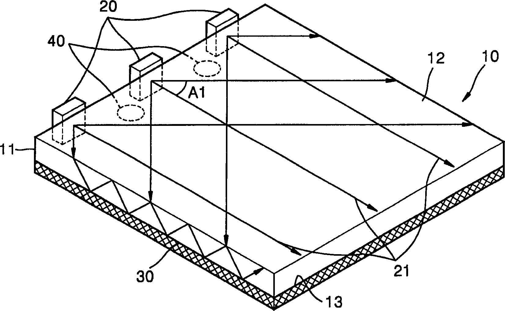
[0028] Figure 4 is a perspective view of an edge-lit backlight system according to a preferred embodiment of the present invention, Figure 5 yes Figure 4 An enlarged perspective view of the light incident portion 120 of the edge-lit backlight system is shown.

[0029] refer to Figure 4 and 5 , the light guide plate 100 is in the shape of a flat plate. Three light emitting diodes (LEDs) 110 are disposed along the effective edge surface 101 of the light guide plate 100 . The light path changing unit 130 is disposed under the light guide plate 100 .

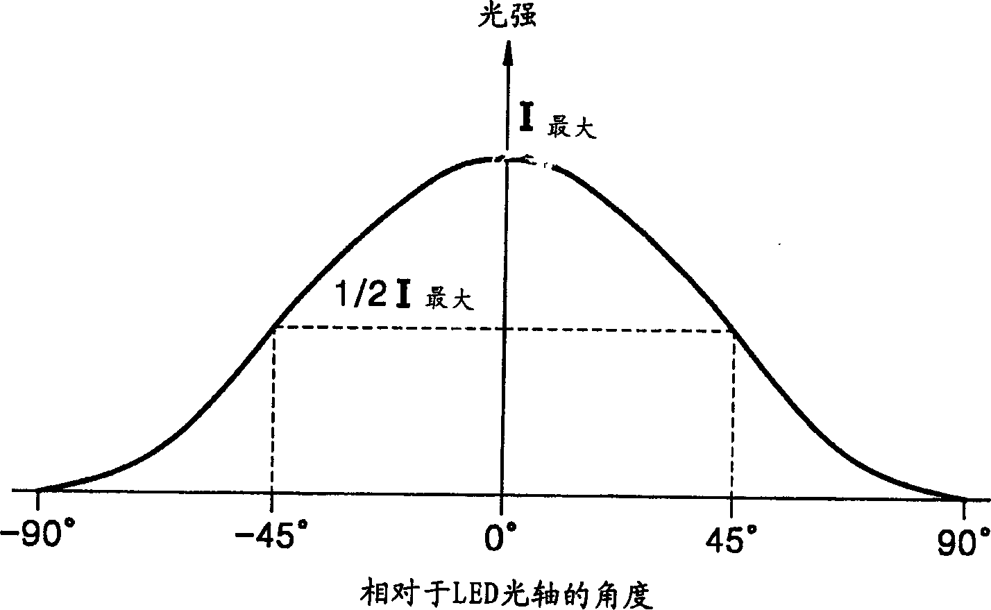
[0030] Each of the LEDs 110 serving as a point light source emits light within a range of ±90 degrees with respect to the optical axis 112 . Such as image 3 As shown, here, the angle at which the LED emits light at half its maximum value is about 45 degre...


PUM

PropertyMeasurementUnit
thicknessaaaaaaaaaa

Abstract

An edge-light type backlight system including a point light source, a light guide panel including a light incident part into which light enters from the point light source and a light emitting surface from which light is emitted, and an optical path-changing unit which changes a propagation path of light traveling inside the light guide panel. The light incident part includes a light incident surface on which a prism pattern is formed, the light incident surface facing the point light source, and first and second surfaces extending from the light incident surface in a direction in which light travels inside the light guide panel and adapted to reflect light passing through the light incident surface to reduce a direction angle, the first and second surfaces being opposite to each other with respect to an optical axis.

Description

technical field [0001] The invention relates to a backlight system, in particular to an edge-emitting backlight system using a light guide plate and a point light source. Background technique [0002] Backlighting systems are used in flat panel displays (FPDs), such as liquid crystal displays (LCDs), to ensure proper illumination or brightness. The backlight system can be divided into direct-emitting backlight units and edge-emitting backlight units according to the configuration of the light source. The direct-emitting backlight unit is a plurality of lighting lamps arranged under the FPD that directly emit light onto the liquid crystal panel, while edge-emitting The type backlight unit is to install lighting lamps along the edge of the light guide plate to emit light to the liquid crystal panel. [0003] Edge-lit backlight systems can employ both rod and point light sources. A representative rod light source is a cold cathode fluorescent lamp (CCFL), which consists of a ...

Claims


Application Information

Patent Timeline
Patent Type & Authority Applications(China)
IPC IPC(8): G02B6/00F21V8/00F21Y101/00G02F1/13357
CPCG02B6/0016G02B6/0018G02B6/0053G02F1/1335
Inventor 闵池泓崔桓荣李文圭金镇焕崔振承
Owner SAMSUNG DISPLAY CO LTD
Learn More