
Method and apparatus for head positioning using servo control in a disk drive

A disk drive and read-write head technology, applied in the field of servo control, can solve the problems of difficult positioning of the read-write head, inability to obtain servo data, etc.

Inactive Publication Date: 2004-11-03
KK TOSHIBA
View PDF2 Cites 4 Cited by
  • Summary
  • Abstract
  • Description
  • Claims
  • Application Information

AI Technical Summary

Problems solved by technology

Therefore, the servo system using the servo data cannot obtain the servo data from the non-servo range, making it difficult to perform normal head positioning operations

Method used


Image

  • Method and apparatus for head positioning using servo control in a disk drive
  • Method and apparatus for head positioning using servo control in a disk drive
  • Method and apparatus for head positioning using servo control in a disk drive

Examples


Embodiment Construction

[0022] Preferred embodiments of the present invention will be described below with reference to the accompanying drawings.

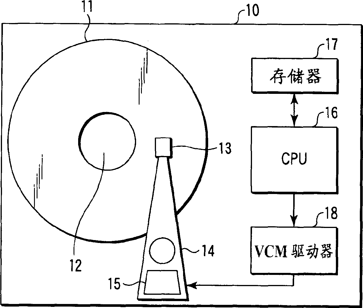
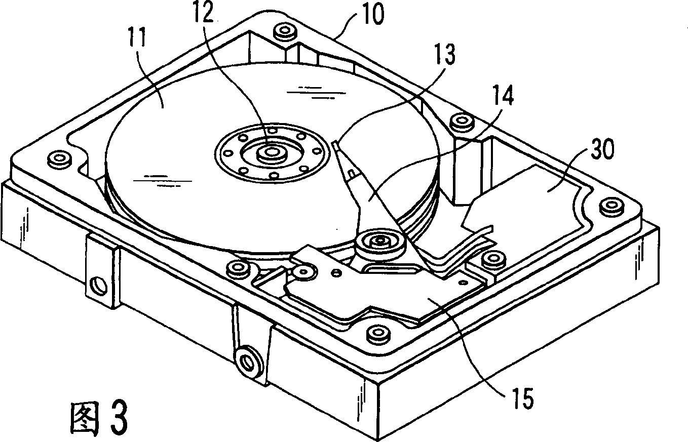
[0023] figure 1 is a block diagram showing an essential part of the disk drive according to the embodiment of the present invention. Fig. 3 is an external view illustrating the disk drive.

[0024] (Disk drive structure)

[0025] The disk drive 10 is, for example, a hard disk drive of a perpendicular magnetic recording method such as figure 1 and 3, and including a disk medium 11, a spindle motor (SPM) 12, and a drive structure of a rotary actuator 14 are also assembled.

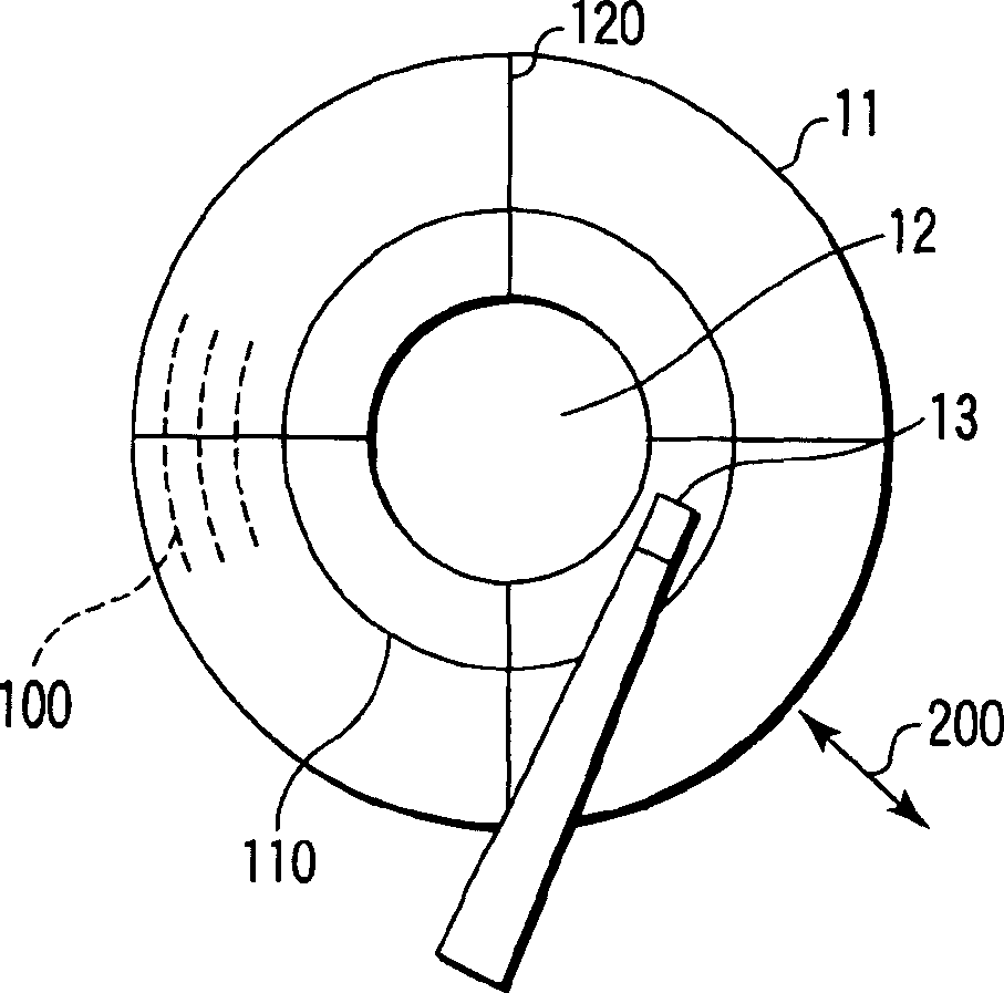
[0026] The head 13 is installed on the actuator 14 so as to move in the radial direction of the disk medium 11 by the driving force of a voice coil motor (VCM) 15 (see figure 2 arrow 200).

[0027] In the head 13, a write head for writing data into the disk medium 11 and a read head for reading data from the disk medium 11 are mounted on the same slider.

[0028] On disk media 1...


PUM


Abstract

There is disclosed a disk drive using a disk medium in which a non-servo range exists. In order to position a head at a target track, a CPU executes a seek operation by normal velocity control using servo data. At this positioning, when the head passes the non-servo range from which no servo data can be obtained, the CPU executes a seek operation by special velocity control to move the head at a velocity calculated based on a moving distance of the non-servo range.

Description

technical field [0001] The present invention relates generally to disk drives and, more particularly, to servo control for head positioning using servo data. Background technique [0002] Hitherto, in disk drives, typically hard disk drives, a servo system has been incorporated in which servo data recorded on the disk medium is used to position the read / write head at a target position on the disk medium. Here, the target location refers to a target track from which data is read or written. [0003] Typically, servo data is recorded on disc media by a servo track writer during the servo writing step included in the process of manufacturing the disc drive. [0004] In a disk drive, a read / write head is mounted on a rotary actuator and moves in the radial direction of the disk medium. Therefore, especially in the inner and outer peripheral regions of the disk medium, a so-called skew angle is caused, indicating the inclination of the head with respect to the data track (the t...

Claims


Application Information

Patent Timeline
Patent Type & Authority Applications(China)
IPC IPC(8): G11B21/08G11B5/55
CPCG11B5/5526
Inventor 矢野耕司
Owner KK TOSHIBA
Learn More