Composite type card connector

A connector and card insertion technology, which is applied in the direction of connection, hybrid reader, two-part connection device, etc., can solve the problems of reduced plug durability, increased installation height, and scratched cards, etc.

Inactive Publication Date: 2004-11-03
YAMAICHI ELECTRONICS
View PDF1 Cites 15 Cited by
  • Summary
  • Abstract
  • Description
  • Claims
  • Application Information

AI Technical Summary

Problems solved by technology

However, in the technique of the above-mentioned publication, in order to allow two different types of cards to be inserted and used in the same multi-connector for cards, it is necessary to perform detailed processing on the cards.
[0005] In addition, it can also be seen that since the overall length, width, and thickness of the card are different in size and size, when setting the contacts suitable for the card, the displacement of the contacts is large when inserting a large card, and when plugging and unplugging In the case of a large card, the card will be damaged by these contacts, and the contact part of the contact will be greatly cut off, which will cause the decrease in plug-in durability. Moreover, in order to prevent the bending of the contact, it is necessary The actual installation height will be increased due to the back groove provided at the front end, etc.

Method used


Image

  • Composite type card connector
  • Composite type card connector
  • Composite type card connector

Examples


Embodiment 1

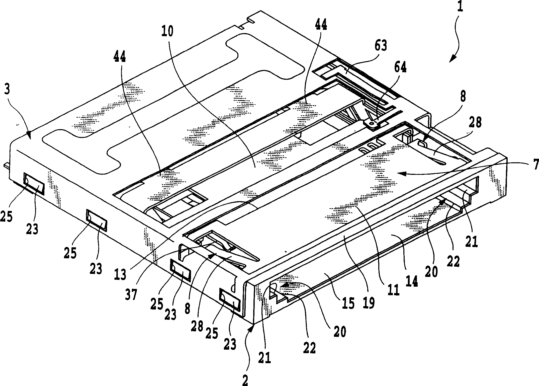
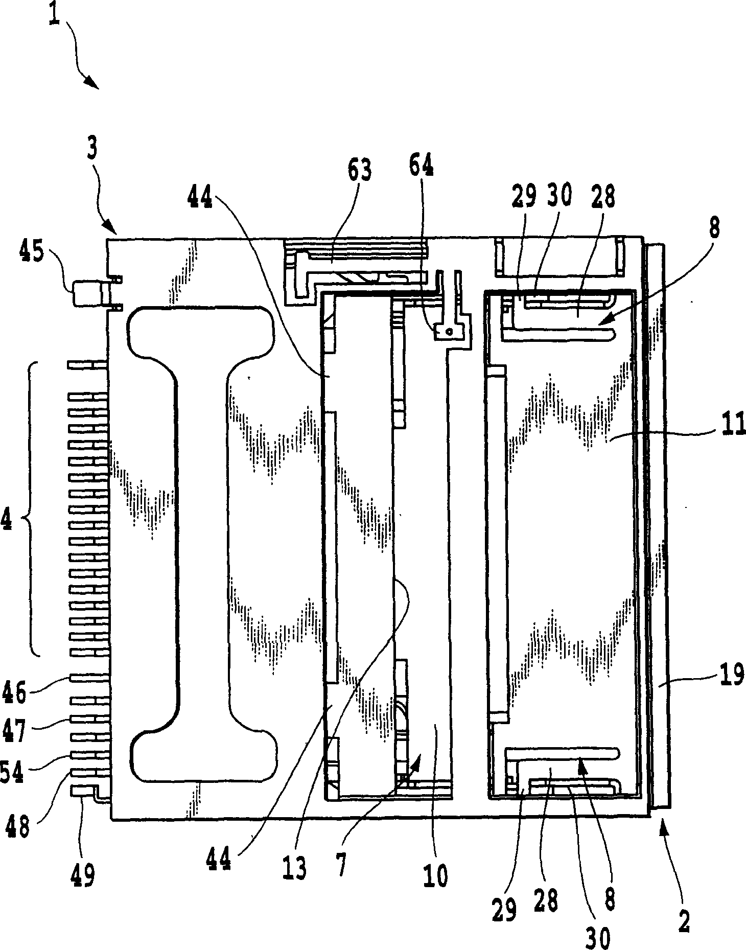
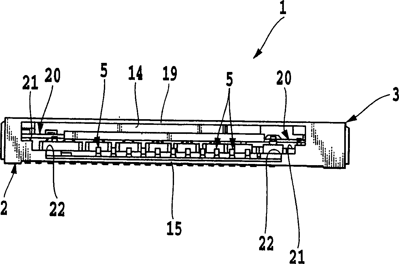
[0085] Figure 1 to Figure 10 It is the figure which shows the embodiment 1 of the multi-connector for cards of the present invention, figure 1 It is a perspective view of the whole composite connector for cards of the present invention seen from the side of the card insertion port, figure 2 is its top view, image 3 It is an end view viewed from the card slot side, Figure 4 yes and right figure 1 The card of the present invention is represented by removing the cover part of the composite connector with the figure 1 The same stereogram, Figure 5 yes means Figure 4 The perspective view of the enlarged part of the lock mechanism part of the composite card connector of the present invention, Image 6 is to remove Figure 4 The top view of the cover part of the card composite connector of the present invention, Figure 7 is its side view, Figure 8 It is a bottom view from the bottom side, Figure 9 is to remove the cover part Figure 4 The perspective view of further...

Embodiment 2

[0142] Figure 41 to Figure 54 It is the figure which shows the embodiment 2 of the composite connector for cards of the present invention, Figure 41 It is a perspective view of the whole composite connector for cards according to Embodiment 2 of the present invention seen from the side of the card insertion port, Figure 42 is true Figure 41 A perspective view of the card composite connector with the cover removed, Figure 43 is true Figure 41 The composite connector for the card further removes the perspective view of the cover part and the movable plate and the operation plate, Figure 44 is from with Figure 43 Relative to the same perspective view looking to the side, Figure 45 is true Figure 41 The composite connector for cards according to Embodiment 2 of the present invention is an end view viewed from the side of the card insertion port when the cover member, the movable plate, and the operation plate are removed. FIG. 46 is for Figure 43 The multi-connec...


PUM


Abstract

A composite type card connector of the present invention includes a connector body, a cover member, first contact members for a small card, second contact members for a large card, and a switching operation mechanism having a movable plate and a operating plate, such that a card-mounting section in the connector body is switched to another one by the switching operation mechanism so that two kinds of cards different in thickness and / or width can be commonly inserted into the same composite type card connector.

Description

technical field [0001] The present invention relates to a compound connector for cards, which is related to electronic devices such as mobile phones, telephone sets, PDA (personal digital assistance), game machines, notebook computers, walkmans, television sets, video recorders, digital cameras, etc. or information terminals. A composite card connector for a machine, in particular to a composite card connector capable of using two types of cards of different sizes. Background technique [0002] In recent years, electronic devices called CPUs or The use of IC cards, PC cards, SD cards, and SIM cards, etc., which are IC chips and IC components for memory, is increasing rapidly, so there is a wide demand for small memories that insert IC cards, PC cards, SD cards, and SIM cards. The card uses a composite connector for the card. In particular, as a composite connector for cards, it is required to make the overall shape of the connector thin, to achieve miniaturization, to have...

Claims


Application Information

Patent Timeline
Patent Type & Authority Applications(China)
IPC IPC(8): G06K17/00G06K7/00G06K13/08H01R13/633H01R27/00
CPCH01R27/00G06K7/0043G06K13/08G06K13/0825G06K7/0013G06K13/0806G06K13/0887G06K7/0021G06K7/0004H01R12/7005H01R23/7005
Inventor 佐藤繁高居阳介
Owner YAMAICHI ELECTRONICS
Why Eureka
Try Eureka