
Low-loss high-selectivity and high-power multicavity filter

A high-selectivity, filter technology, applied in waveguide-type devices, electrical components, circuits, etc., can solve the problems of increased processing difficulty, complex processing technology, large insertion loss, etc., to reduce the debugging workload and improve the selection. The effect of performance, low loss selectivity

Inactive Publication Date: 2004-11-10
庄昆杰
View PDF0 Cites 3 Cited by
  • Summary
  • Abstract
  • Description
  • Claims
  • Application Information

AI Technical Summary

Problems solved by technology

The design and manufacture of this kind of filter are relatively mature, and the insertion loss is also small. The problem is that the coupling between adjacent resonators is a fixed design, and the passband width cannot be adjusted, which is not conducive to the design and manufacture of multi-variety series products. , and when the passband width is required to be narrowed, the distributed coupling region will be lengthened accordingly, increasing the size of the filter
The problem is that the screw device is relatively clumsy, and the insertion loss is also relatively large. Moreover, when there are many requirements for the resonant cavity, the processing difficulty increases, and the technical debugging work is quite cumbersome, complicated and time-consuming.
Its disadvantages are mainly large material consumption, complex processing technology, high requirements, high difficulty, low production efficiency and high production cost.

Method used


Image

  • Low-loss high-selectivity and high-power multicavity filter
  • Low-loss high-selectivity and high-power multicavity filter
  • Low-loss high-selectivity and high-power multicavity filter

Examples


Embodiment Construction

[0024] The present invention will be described in detail below with reference to the accompanying drawings and examples. However, the invention is not limited to the examples given.

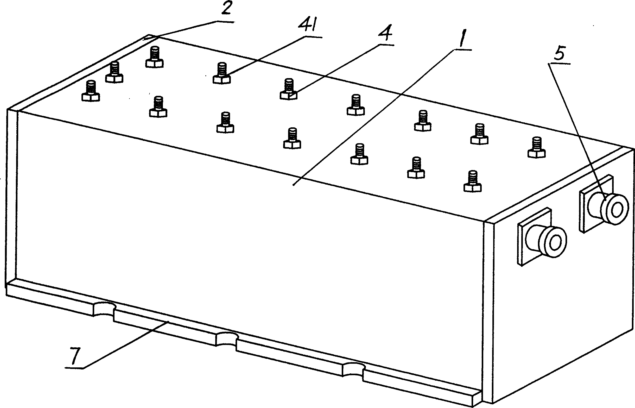
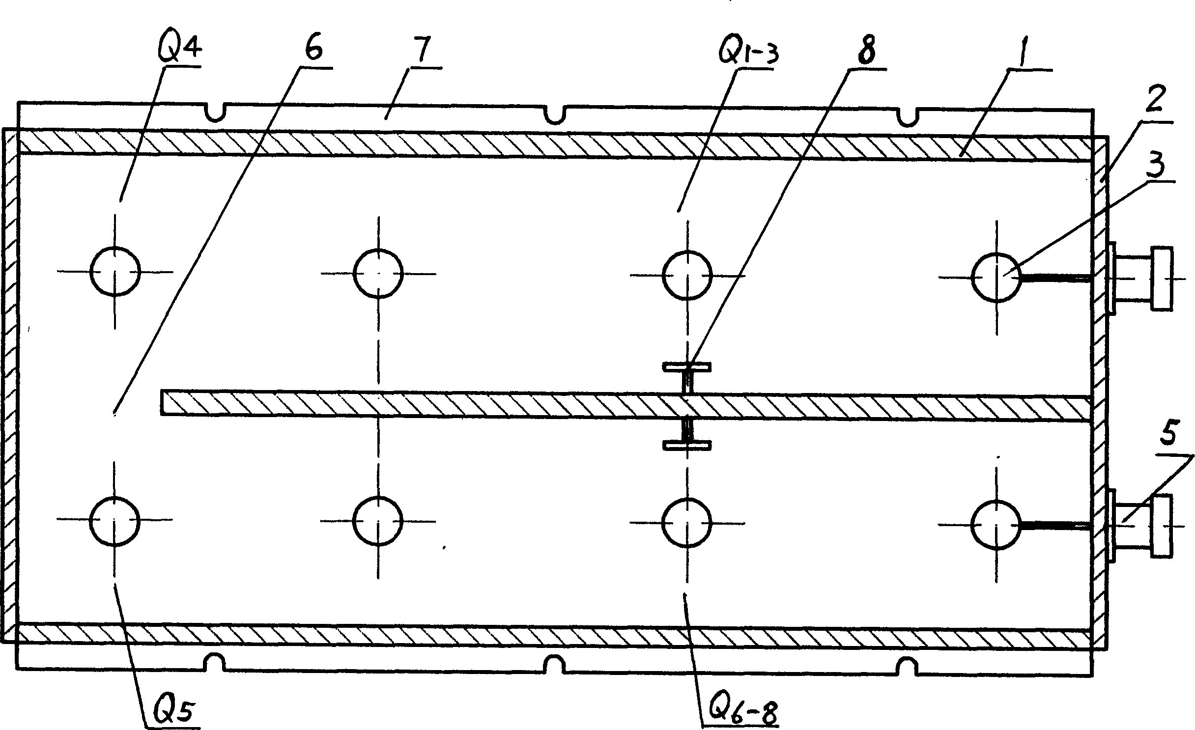
[0025] Such as figure 1 with figure 2 As shown, Example 1 is an eight-cavity filter, which has a resonant cavity main body 1, a cover plate 2, an inner conductor 3, a resonant frequency adjustment screw 4, and an input and output interface device 5. The main body 1 is flat Q1-8, and the resonant cavities on both sides Q1-3 and Q6-8 are comb-shaped symmetrical distributed coupling cavities, and the two resonant cavities Q4 and Q5 in the middle are coaxial resonant cavities with centralized coupling. Figure 6 shows the gaps of Q4 and Q5 cavity spacers, 41 7 is the adjustment screw for inter-cavity compensation, and 7 is the positioning edge for filter installation. In the embodiment shown in the figure, a further feature is that there is a cavity coupling device 8 located between the third and ...


PUM


Abstract

The invention is a low-loss, high-selectivity, high-power, multicavity filter, comprising a resonant cavity main body, cover plates, inner conductor, resonance frequency adjusting bolt, and I / O interface device, where the main body is a parallel one-piece birectangular cavity, the covers are situated at two ends of the birectangular cavity, and there are even resonant cavities in the main body, in which the resonant cavities on two sides are comb symmetrically distributed coupled ones and the two cavities in the middle are centralized coupled coaxial ones. It adopts the organic combination mode of distributed and centralized couplings, which gives consideration to both low -loss and high-selectivity requirements, has the advantages of simple structure, small bulk, primary molding, simplified process, a little material consumption, good product consistency, high production, and low cost, can design the corresponding moulds according to difference in filter performance and bulk, implementing multiple variety production to scale. It has a widely use and provides an ideal kernel filter device for wireless communication engineering.

Description

Technical field [0001] The invention relates to a microwave filter used in the field of wireless communication, in particular to a low-loss and high-selectivity multi-cavity filter capable of passing high power. Background technique [0002] In all kinds of modern wireless communication equipment, such as GSM / CDMA / PCS / DCS mobile communication high-power wireless base station, digital trunking high-power wireless base station, etc., all need a kind of high-power, high-selectivity, and loss. The filter technology as small as possible, and various key components designed based on this technology, such as the transceiver duplexer placed in the base station, the tower top amplifier placed under the base station antenna, and the output port of the base station for Combiner splitter for high power amplification and so on. However, as far as the current technical level is concerned, for a filter capable of passing high power, there are still many technical difficulties in order to ...

Claims


Application Information

Patent Timeline
IPC IPC(8): H01P1/207
Inventor 庄昆杰
Owner 庄昆杰
Learn More