Gain factor and position determination system

A technology of coefficient and system gain, applied in the direction of radio wave measurement system, measurement device, electrical device, etc., can solve problems such as system recalibration

Inactive Publication Date: 2004-11-10
NORTHERN DIGITAL
View PDF0 Cites 7 Cited by
  • Summary
  • Abstract
  • Description
  • Claims
  • Application Information

AI Technical Summary

Problems solved by technology

Thus, the system must be manually recalibrated

Method used


Image

  • Gain factor and position determination system
  • Gain factor and position determination system
  • Gain factor and position determination system

Examples


Embodiment Construction

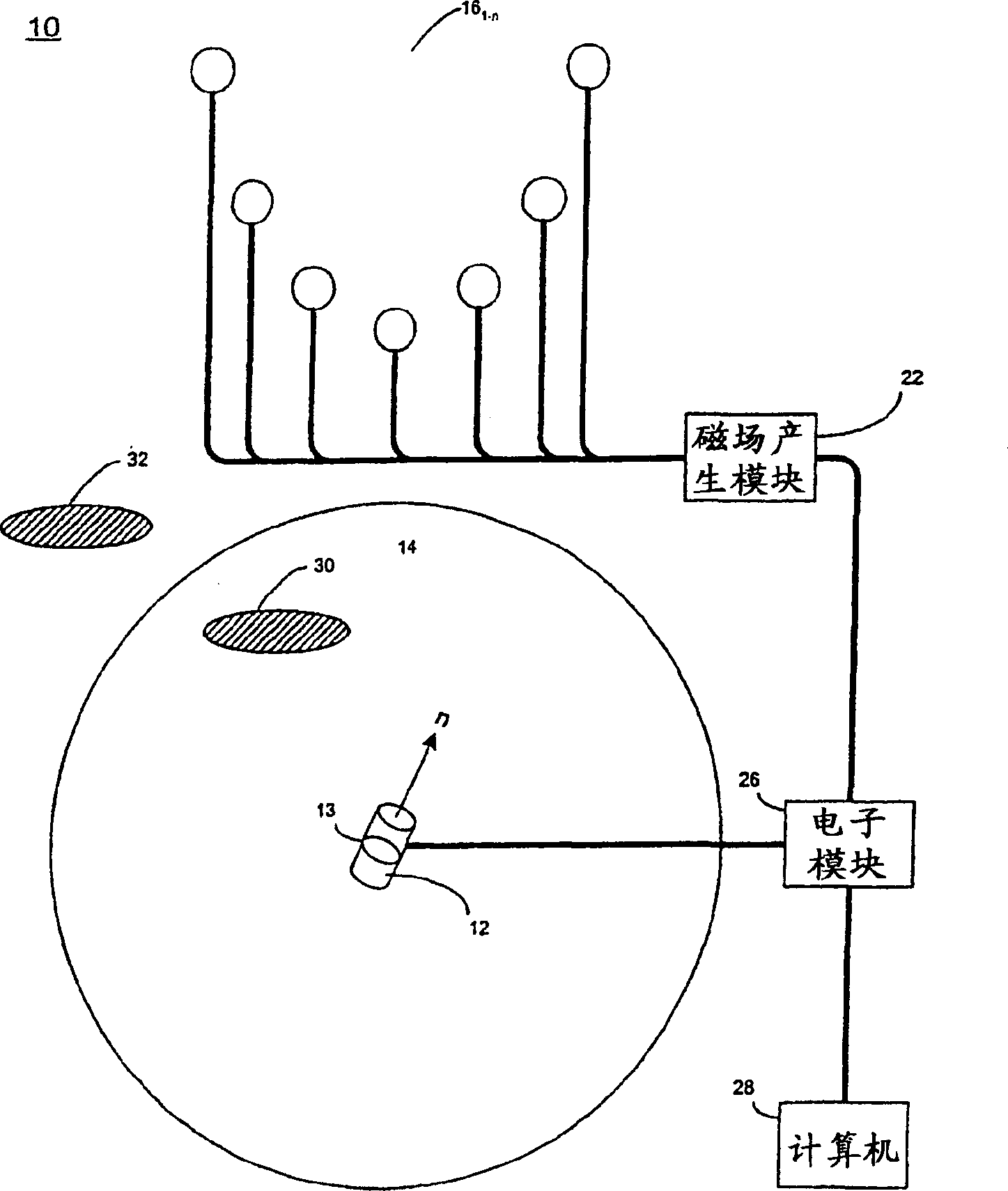
[0024] see figure 1 and figure 2 , schematically represents a system 10 for determining the position, orientation and system gain factor of a movable probe 12 using magnetic field measurements. The movable probe 12 is positioned within a patient's body 14 (eg, within the patient's body). System 10 also includes a plurality of magnetic field sources 16 1-n (eg small induction coils), which are located outside the volume 14 . Magnetic field source 16 1-n Driven by a magnetic field generating module 22 such as an AC or DC current source. Note that although seven magnetic field sources are shown, this is for illustration only and not as a limitation of the invention.

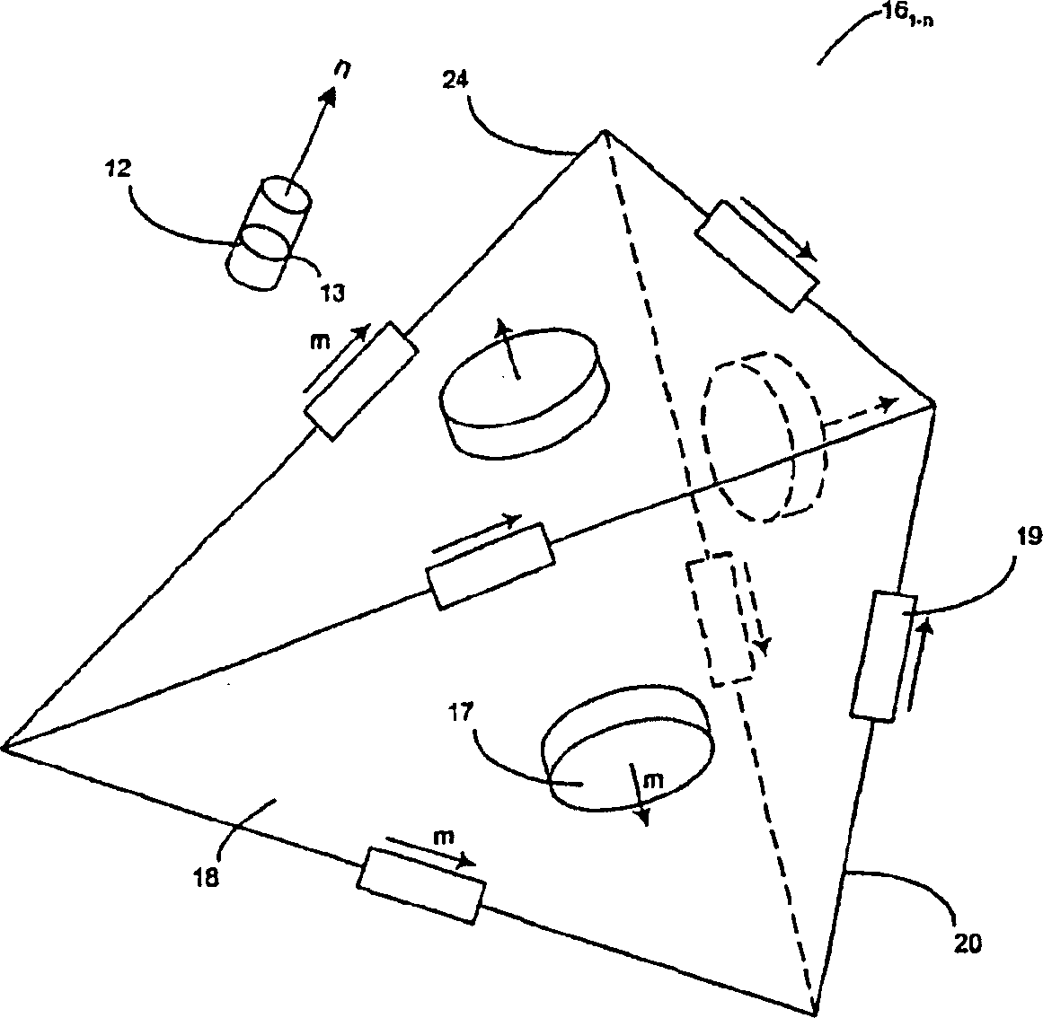
[0025] figure 2 is a side view of the system 10 showing the magnetic field source 16 1-n and the three-dimensional orientation and position of the probe 12. 16 per magnetic field source 1-n Either a surface-mounted magnetic field source 17 on the surface 18 of the regular tetrahedron 24 or an edge-mounted...


PUM


Abstract

A system for determining the position, orientation and system gain factor of a probe includes a plurality of magnetic field sources and at least one magnetic field sensor, such that a combination of a magnetic field sensor and a magnetic field source generates a unique measured magnetic field value. The system includes a probe whose gain, position, and orientation affect these unique measured magnetic field values. A processor is configured to receive and iteratively process these unique measured magnetic field values to determine a system gain factor indicative of the gain of the probe and a plurality of location factors indicative of the position and orientation of the probe. The number of unique measured magnetic field values generated must be at least equal to the sum of the number of gain and location factors calculated.

Description

technical field [0001] The present invention relates to a system for determining the position and orientation of an object and the gain factor of the system using a magnetic field. Background technique [0002] As is known in the art, the system can indirectly determine the position and orientation of an object using magnetic field measurements. These systems are useful, for example, in the medical field because they enable precise positioning of objects within a patient's body with only minimal invasiveness to the body. The intrusion involves placing a small probe near the object to be located. The three-dimensional position and orientation of the probe is then determined from its effect on the magnetic field measurement. [0003] The probe can be a magnetic field source or a magnetic field detector. If the probe is the source, a detector outside the body measures the magnetic field generated by the probe. If the probe is the detector, a magnetic field source outside th...

Claims


Application Information

Patent Timeline
IPC IPC(8): G01B7/00A61B5/06A61B5/07G01V3/08
CPCA61B5/06G01V3/081A61B5/062
Inventor 斯蒂芬·R·基尔希汉斯·R·希尔德克里斯蒂·J·希林
Owner NORTHERN DIGITAL
Why Eureka
Try Eureka