Coupling device for medical instrument or medical power-tool chuck

a technology of powertool chuck and coupling device, which is applied in the direction of spanners, wrenches, medical science, etc., can solve the problems of blood and other tissue getting caught, inability to ensure that all residues are removed, and complex mechanisms of existing couplings, etc., to achieve easy and thorough cleaning and sterilization, and quick and easy exchange of tool inserts

Inactive Publication Date: 2018-10-09
41MEDICAL AG
View PDF15 Cites 3 Cited by
  • Summary
  • Abstract
  • Description
  • Claims
  • Application Information

AI Technical Summary

Benefits of technology

[0008]It is the object of the invention to create a coupling for a medical instrument which allows a quick and easy exchange of tool-inserts and which may be very easily and thoroughly cleaned and sterilized.

Problems solved by technology

Existing couplings comprise complex and expensive mechanisms which have to fulfil different functional requirements.
Blood and other tissue may get caught in theses mechanisms and it is impossible to guarantee that all residues are removed before the instrument is used in a next surgery.

Method used


Image

  • Coupling device for medical instrument or medical power-tool chuck
  • Coupling device for medical instrument or medical power-tool chuck
  • Coupling device for medical instrument or medical power-tool chuck

Examples


second embodiment

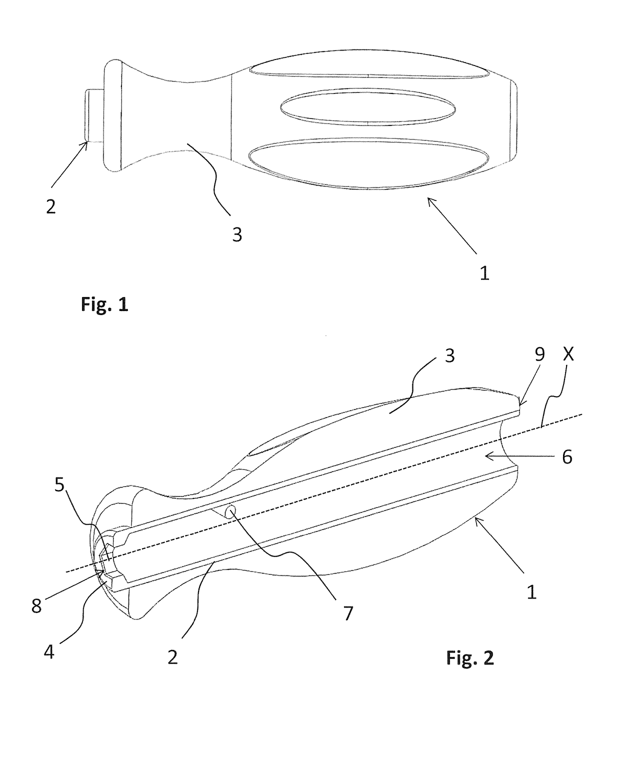
[0078]FIGS. 7a and 7b show a medical tool 1 according to the present invention. FIG. 7a shows the handle 3 with the coupling body 2 integrated therein. At the first end, the coupling body 2 comprises anti-rotation faces 5, but no seat 4. Otherwise, the handle 3 and the coupling body 2 have the same features as the embodiment as shown in FIGS. 1 to 6.

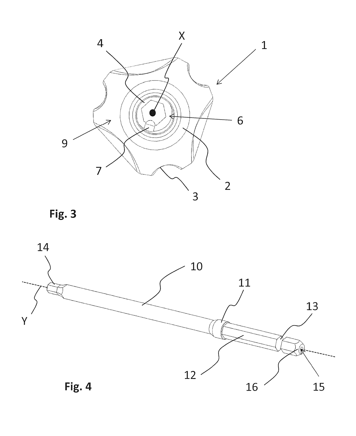
[0079]The tool-insert 10 is depicted in FIG. 7b. In contrast to the embodiment as shown in FIGS. 1 to 6, the tool-insert 10 comprises rounded faces 17. Rounded faces 17 do not include a flat surface as the tool-insert faces 12, but rather exhibit a curved surface in the direction of the central axis Y. This curvature of the rounded faces 17 facilitates the inclination of the tool-insert 10 relative to the coupling body 2, as is shown in FIG. 8a. Hence, contrary to the embodiment as shown in FIGS. 1 to 6, where inclination of the tool-insert 10 relative to the coupling body 2 is relying on some play between the anti-rotation faces 5 and t...

first embodiment

[0080]FIGS. 8a to 8c show the assembly steps for a medical tool 1 according to the embodiment as depicted in FIGS. 7a and 7b. FIG. 8a already shows the second step of the assembly, as the first step is identical to the first step as shown for the medical tool 1 on FIG. 6a. As may be seen on this figure, the cooperation of the rounded faces 17 with the faces 4 facilitates the inclination of the tool-insert 10 relative to the coupling body 2.

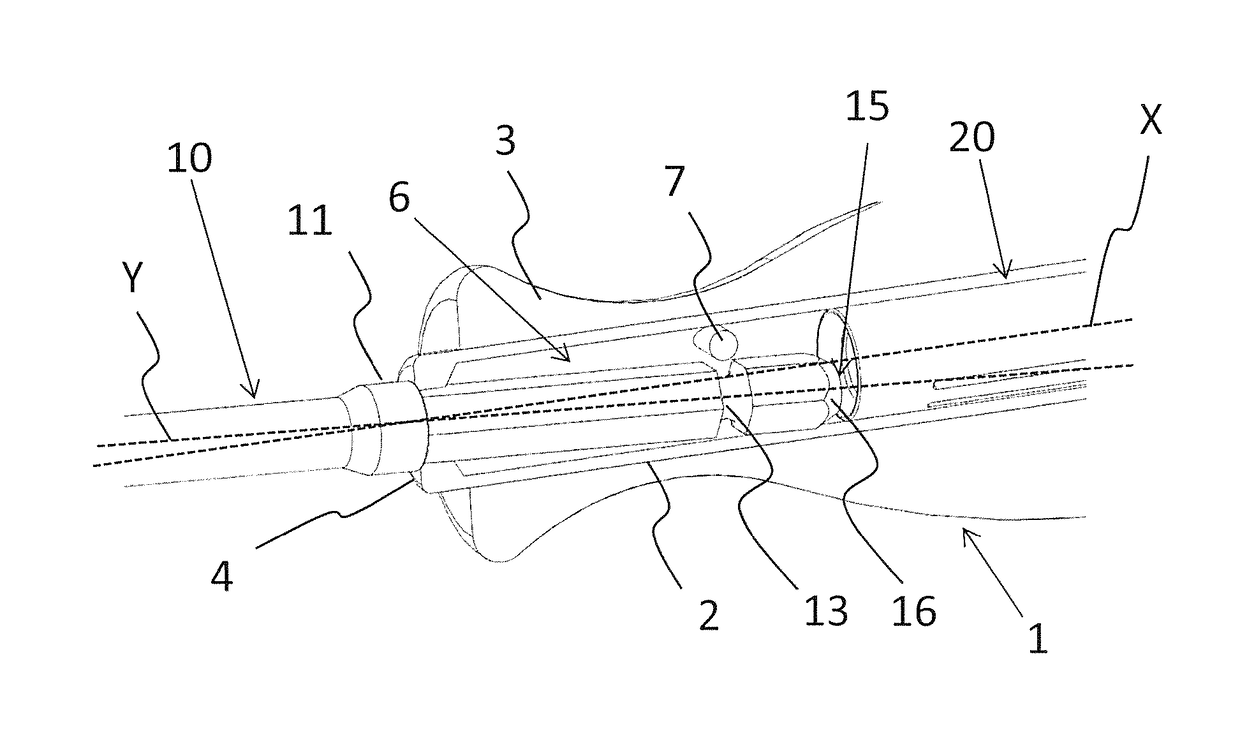
[0081]As may be seen on FIG. 8b, upon re-alignment of the central axis Y with the working axis X, the protrusion 7 engages the groove 13. However, in difference to the first embodiment as shown in FIGS. 1 to 6, the insert seat 11 cooperates with the protrusion 7 rather than with a seat 4. Therefore, any impaction forces exerted on tool-insert 10 will be transmitted to the coupling body 2 via the interaction of the insert seat 11 and the protrusion 7.

[0082]Analogous to the first embodiment, the locking-body 20 is finally advanced towards the first ...


PUM


Abstract

The present application relates to a coupling device for a handle (3) of a medical tool (1) or medical power-tool chuck (30). The coupling device comprises a coupling-body (2) including a bore (6), a working axis (X) extending along said bore (6) and a seat (4) arranged at a first end (8) of said bore for receiving a tool-insert (10) with a central axis (Y) at an angle in reference to the working axis (X). The coupling-body (2) further comprises a protrusion (7) arranged within said bore (6), said protrusion (7) being configured to engage a groove (13) of the tool-insert (10) upon alignment of the central axis (Y) with the working axis (X). The engagement of the protrusion (7) with said groove (13) locks the tool-insert (10) within said coupling body (2).

Description

TECHNICAL FIELD[0001]The invention relates to a coupling device for a handle of a medical instrument or medical power-tool chuck as well as to a method for assembling a tool-insert into a coupling device of a medical instrument.BACKGROUND ART[0002]In many fields of surgery, for example orthopaedics, traumatology, spine surgery and dental surgery different tools, such as screwdriver shafts, drills, awls, probes, chisels, rasps are combined with handles.[0003]In order to reduce costs, weight of instrument sets and number of instruments, tools are often designed as modular systems, featuring a small number of handles in different sizes and types which may be combined with a large number of different tool-inserts. For quick assembly and disassembly of different tool inserts during surgery, state of the art handles feature quick-couplings.[0004]For example, GB 144,607 (Kunz Otto) discloses a tool with interchangeable blades. An offset portion of a blade provided on one side remote from t...

Claims


Application Information

Patent Timeline
Patent Type & Authority Patents(United States)
IPC IPC(8): A61B17/16B25B23/00A61B17/88B25G3/04B25G3/18A61B17/00
CPCA61B17/162A61B17/16A61B17/88B25B23/0035B25G3/18B25G3/04A61B2017/00477A61B17/8875A61B2017/0046
Inventor OVERES, TOMFRIGG, ROBERT
Owner 41MEDICAL AG
Why Eureka
Try Eureka