
Riding vehicle

A technology for ride-on vehicles and car bodies, applied to vehicle parts, motorcycles, bicycles, etc., can solve problems such as cooling water pipe obstacles, rotating support shaft obstacles, various operations, etc., and achieve the effect of preventing high temperature

Active Publication Date: 2008-06-18
YAMAHA MOTOR CO LTD
View PDF7 Cites 0 Cited by
  • Summary
  • Abstract
  • Description
  • Claims
  • Application Information

AI Technical Summary

Problems solved by technology

[0006] Therefore, when the drive unit is rotatably supported or detached from the vehicle body by operating the rotatable support shaft, the cooling water pipe may become an obstacle.
On the other hand, if the cooling water pipe is connected or disconnected from the internal combustion mechanism and the radiator, the rotation support shaft may become an obstacle.
That is, when carrying out installation, maintenance, and inspection of the rotary support shaft and the cooling water pipe, which are the above-mentioned vehicle components, these parts may interfere with each other, so the above-mentioned various operations may be complicated.

Method used


Image

  • Riding vehicle
  • Riding vehicle
  • Riding vehicle

Examples


Embodiment Construction

[0053] In order to explain the present invention in more detail, an embodiment thereof will be described using the drawings.

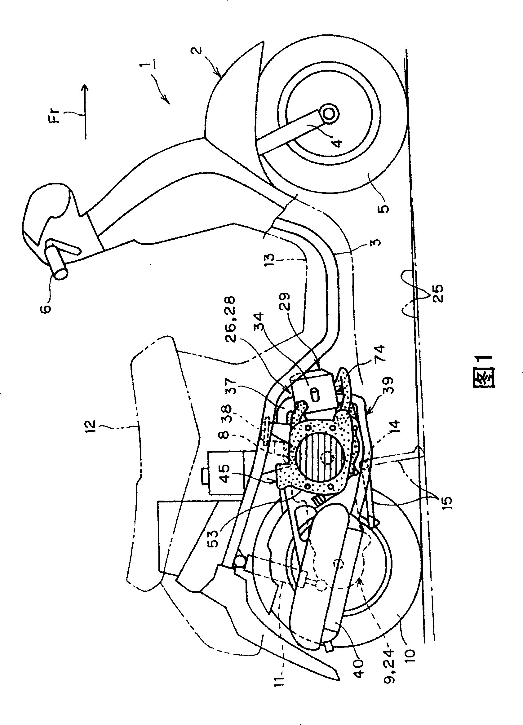
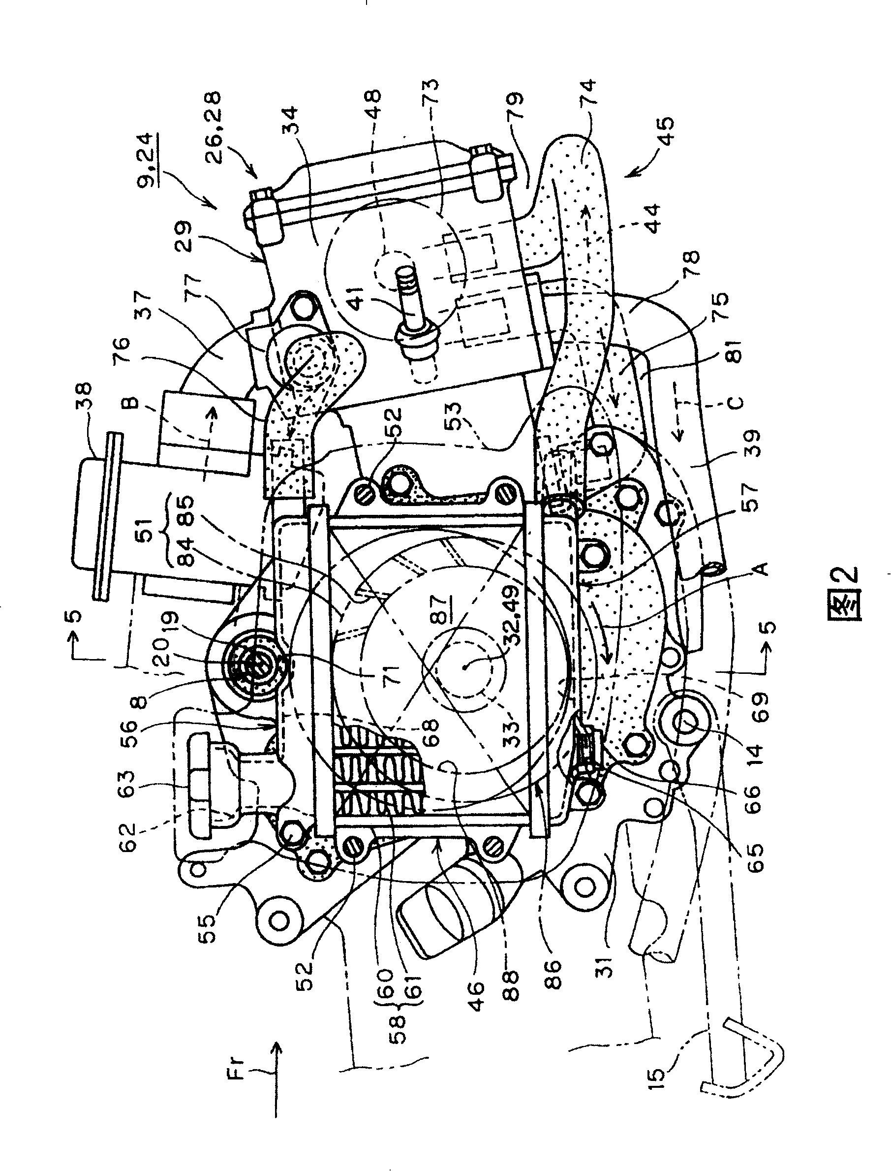
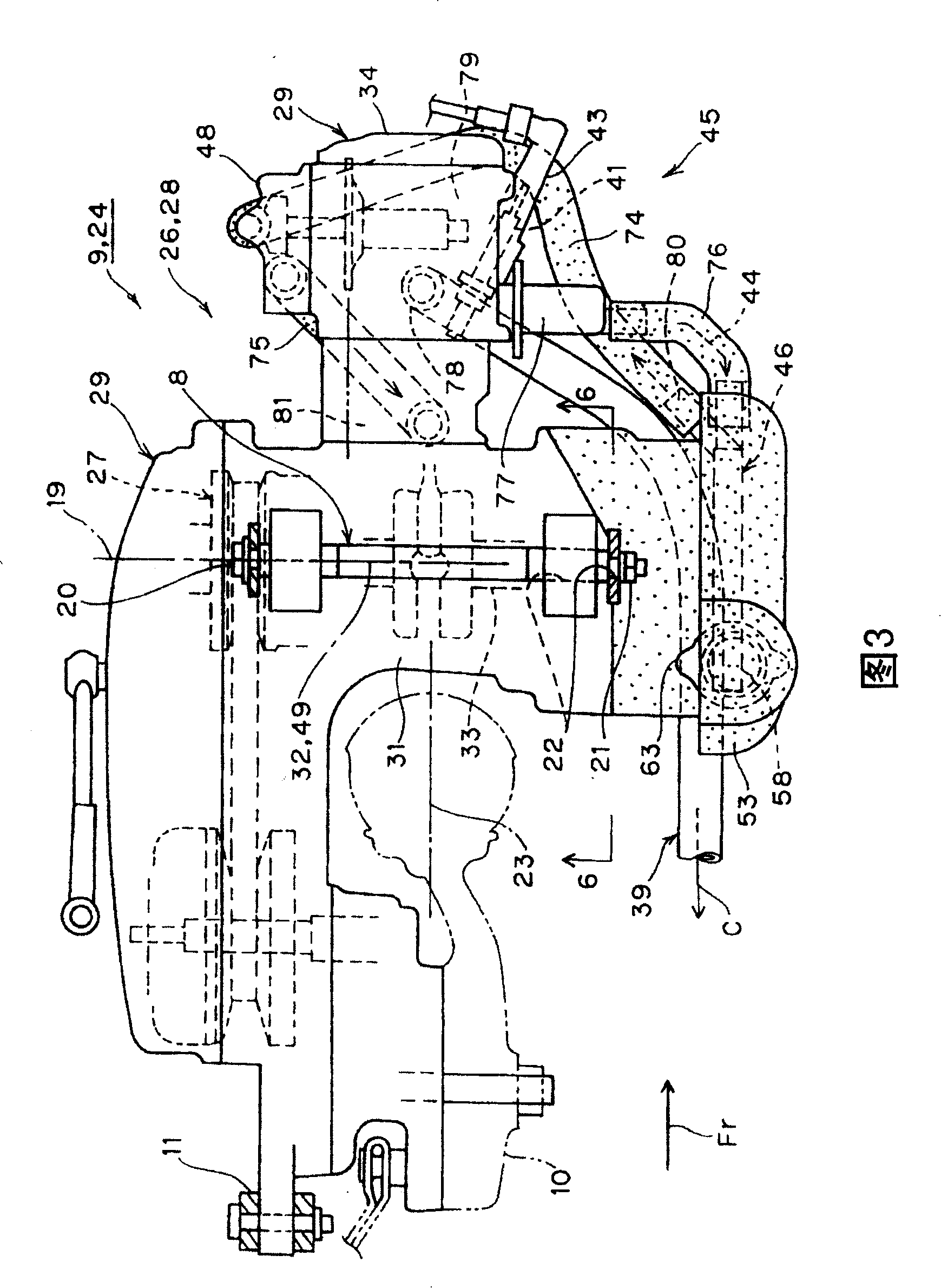
[0054] In FIGS. 1 to 3 , reference numeral 1 is a scooter-type motorcycle as an example of a saddle-ride vehicle, and an arrow Fr indicates the front of the traveling direction of the vehicle 1 . In addition, left and right as described below means the width direction of the vehicle body 2 of the vehicle 1 facing the above-mentioned front.

[0055] The above-mentioned vehicle body 2 has: a vehicle body frame 3 constituting the skeleton of the vehicle body 2; a front fork 4 which is steerably attached to the front end of the vehicle body frame 3; and a front wheel 5 which is supported on the vehicle body 2. The lower end of the front fork 4; the steering handle 6, which is supported on the upper end of the front fork 4; the rear arm 9, which extends in the longitudinal direction of the vehicle body 2, that is, in the front-rear direction, and can be mov...


PUM


Abstract

The purpose of this invention is to facilitate respective works for assembling, maintaining and inspecting regarding constituent parts of a vehicle. A front wheel 5 which is supported by the front section of the vehicle body 2, a driving unit 24 the front section side of which is pivoted by a pivot 8 extending in the width direction of the vehicle body 2 so that the rear section side may be rockable in the vertical direction, and a rear wheel 10 which is supported by the rear section of the driving unit 24 are provided. The driving unit 24 is equipped with an internal combustion engine 28 for running-driving, a radiator 46 which cools a cooling water 44 for cooling the internal combustion engine 28, and a cooling water tube 76 which communicates the radiator 46 and a water jacket 47 which is formed on the internal combustion engine 28 with each other. When the vehicle body 2 is seen from the side surface, the pivot 8 is arranged above the middle section in the longitudinal direction of the radiator 46, and the whole of the cooling water tubes 74 and 76 are arranged on the front side of the pivot 8.

Description

technical field [0001] The present invention relates to a ride-on vehicle in which a drive unit swingably and rotatably supported on a vehicle body has an internal combustion mechanism, a radiator for cooling the internal combustion mechanism, and a cooling water pipe connecting the radiator and the internal combustion mechanism. type vehicles. Background technique [0002] As a prior art, the saddled vehicle described above is disclosed in JP-A-2000-203483. According to this publication, a saddle-riding vehicle is provided with a front wheel which is supported (mounted) on the front of the vehicle body; Rotationally supported) on the above-mentioned vehicle body, so that the rear side can swing up and down; and the rear wheel, which is arranged on the center of the width direction of the above-mentioned vehicle body frame, is supported on the rear of the above-mentioned driving unit. [0003] The driving unit has: an internal combustion mechanism for driving; a radiator, ...

Claims


Application Information

Patent Timeline
Patent Type & Authority Patents(China)
IPC IPC(8): B62M7/02F01P3/18B62J99/00B60K11/02B60K11/06B62K11/00
Inventor 猪森俊典牧野浩直
Owner YAMAHA MOTOR CO LTD
Learn More