
Method and apparatus for controlling a display device

A technology for display elements and subfields, applied in video processing methods and improved control of display drivers, and in the field of reducing flicker effects in large areas, can solve problems such as not having subfields

Inactive Publication Date: 2004-11-10
THOMSON LICENSING SA
View PDF4 Cites 11 Cited by
  • Summary
  • Abstract
  • Description
  • Claims
  • Application Information

AI Technical Summary

Problems solved by technology

As a result, there is no subfield with the same subfield weight in the subfield structure

Method used


Image

  • Method and apparatus for controlling a display device
  • Method and apparatus for controlling a display device
  • Method and apparatus for controlling a display device

Examples


Embodiment Construction

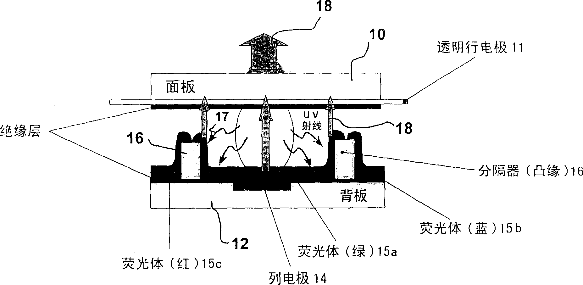
[0035] exist figure 1The principle structure of a plasma cell in so-called matrix plasma technology is shown in . Reference numeral 10 denotes a panel made of glass. Reference numeral 11 denotes a transparent row electrode. Reference numeral 12 denotes a rear panel of the display panel. There are two insulating layers 13 for isolating the face plate and the back plate. Column electrodes 14 perpendicular to the row electrodes 11 are integrated in the backplane. The interior of the unit is composed of luminescent substances 15 (phosphors) and separators 16 for separating fluorescent substances of different colors (green 15a) (blue 15b) (red 15c). The UV radiation caused by the discharge is denoted by reference numeral 17 . Light emitted from the green phosphor 15a is indicated by an arrow with reference numeral 18 . From this structure of the PDP cell, it is clear that there are three plasma cells required for the three color components RGB in order to produce the colors o...


PUM


Abstract

The invention deals with the large area flicker effect reduction in display devices like plasma display panels, in which the light output is controlled by small pulses over a whole frame period and the amount of small pulses determine the brightness of the light output. The invention proposes an adaptation of the known principle of sub-field grouping for large area flicker reduction for the specific sub-field coding process called incremental sub-field coding, in which only those sub-field code words are taken for display driving having the characteristic that there is never a sub-field inactivated between two activated sub-fields or never a sub-field is activated between two inactivated sub-fields.For this specific sub-field coding it is proposed to make the sub-field grouping in a simple manner, where all the odd sub-fields are grouped together in one group (G1) and all the even sub-fields are grouped together in a second group (G2).

Description

technical field [0001] The present invention relates to a method and an apparatus for controlling a display device such as a matrix display like a plasma display panel (PDP), a display device with a digital micromirror array (DMD), and a light emission based All kinds of displays etc. based on space modulation (Pulse Width Modulation) principle. [0002] More particularly, the present invention relates to a class of video processing methods for improved image quality and improved control of display drivers, in particular for the reduction of large area flicker effects. Background technique [0003] Plasma display technology makes it possible to obtain a flat color panel with a large size and a limited depth without any viewing angle limitation. The display can be much larger in size than conventional CRT picture tubes allow. [0004] Plasma display panels use a matrix array of discharge cells that can only be "on" or "off". Also unlike a CRT or LCD that expresses gray lev...

Claims


Application Information

Patent Timeline
Patent Type & Authority Applications(China)
IPC IPC(8): H04N5/66G09G3/20G09G3/291G09G3/292G09G3/293G09G3/296H04N5/21H04N5/70H04N9/30
CPCG09G2320/0247H04N9/30G09G2320/0266G09G3/2029G09G3/2051G09G3/204H04N5/70G09G3/2927G09G2320/0276G09G2320/0261H04N5/21G09G3/2937G09G3/291G09G3/296
Inventor 卡洛斯·科雷亚塞巴斯蒂安·魏特布吕克迪代·杜瓦扬乔纳森·凯瓦克
Owner THOMSON LICENSING SA
Learn More