Device for detecting difference in warp tension of a loom

A difference detection and warp technology, applied in the field of detection devices, can solve problems such as inability to measure displacement correctly, inability to measure accurate distance, and rocker structure cannot measure with high precision, so as to simplify the calculation and processing of detection signals and reduce parts The effect of the number of pieces

Inactive Publication Date: 2004-12-01
TSUDAKOMA KOGYO KK
View PDF3 Cites 4 Cited by
  • Summary
  • Abstract
  • Description
  • Claims
  • Application Information

AI Technical Summary

Problems solved by technology

As a result, the former cannot correctly measure the displacement of the warp corresponding to the change in warp tension
[0006] In addition, in the optical detection device, if the wind wool adheres to the light-transmitting surface or the light-receiving surface of the detector and the warp yarn as the detection object, the light from the detector may be reflected by the wind wool, and as a result, the measurement cannot be performed. Exact distance from horizontal datum part to datum plane
[0007] In particular, in the device for measuring the distance between the reference plane provided on the rocker and the horizontal reference part of the detection device, although the measurement accuracy is required to be around 0.1 mm to 0.01 mm, although the optical detection device itself has such a high measurement Accuracy, but the rocker structure of the above-mentioned device cannot measure the distance between the reference plane and the horizontal reference part with high precision

Method used


Image

  • Device for detecting difference in warp tension of a loom
  • Device for detecting difference in warp tension of a loom
  • Device for detecting difference in warp tension of a loom

Examples


Embodiment Construction

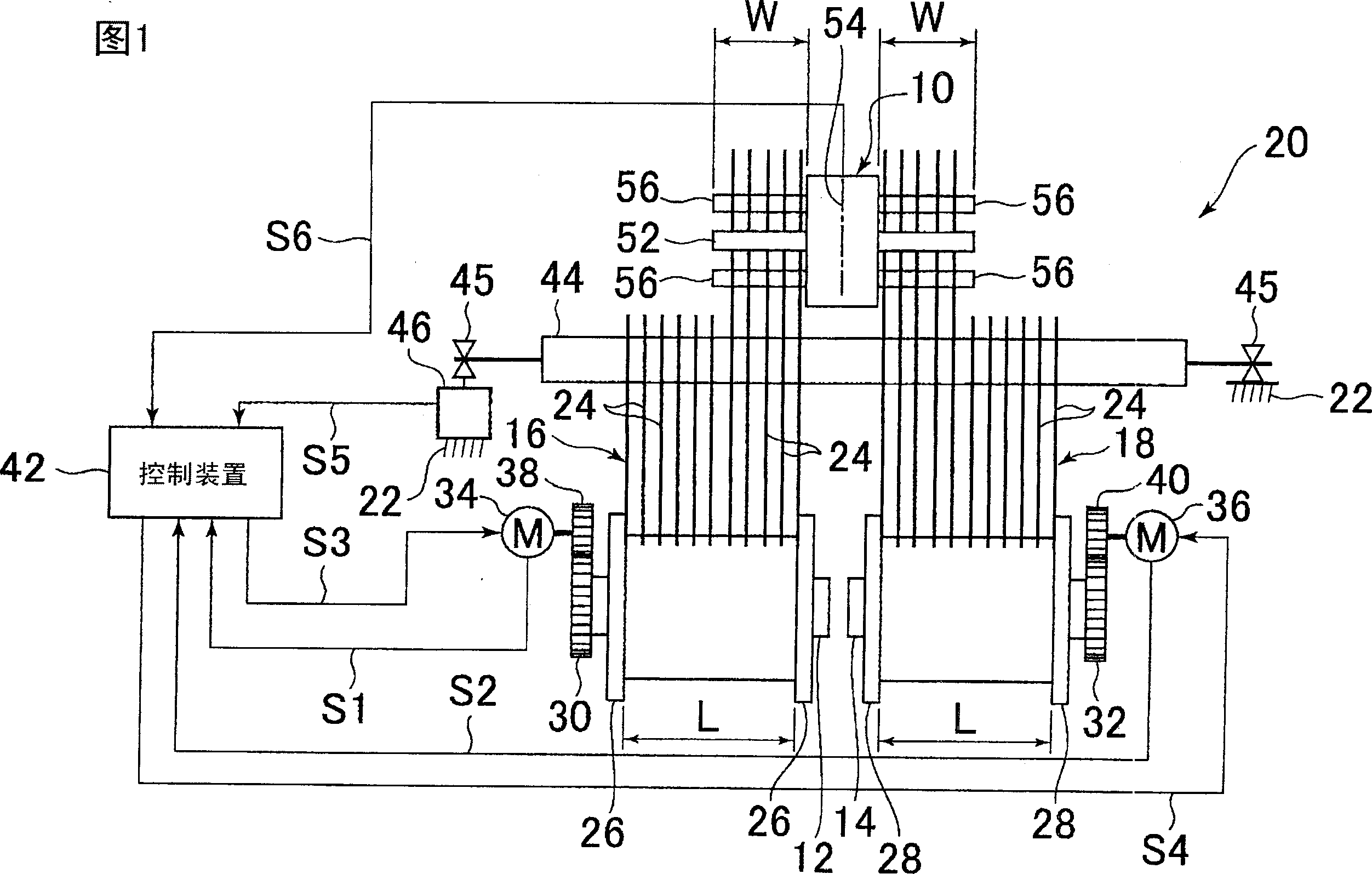
[0026] Referring to Fig. 1, warp yarn tension difference detecting device 10 detects the warp yarn tension difference of two warp yarn plane bundles 16 and 18 sent out from two warp yarn reels 12 and 14 along the adjacent weft insertion direction.

[0027] The warp yarn reels 12 and 14 are arranged on the frame 22 of the loom 20 at a certain interval along the weft insertion direction and make their rotation axes coincide. Warp yarn reels 12 and 14 each wind several warp yarns 24, and these warp yarns 24 are sent out along the adjacent weft insertion direction in the form of warp yarn plane bundles 16 and 18 arranged in parallel in a plane bundle shape. The warp roll width L of the warp reels 12 and 14 is the same.

[0028] The warp reels 12 and 14 are provided with detachable warp beam flanges 26 and 28 at both ends thereof, and detachable warp reel gears 30 and 32 are attached to the opposite sides.

[0029] Warp yarn reel gears 30 and 32 are respectively engaged with gears...


PUM


Abstract

A device for detecting difference in warp tension of a plurality of warp sheets let off side by side from different warp beams in the weft inserting direction detects a tension receiver having a plurality of contact faces which are individually in contact with the boundary side end portions of adjoining warp sheets at intervals in the weft inserting direction, and detects an angular rotational displacement or angular rotational force of the tension receiver around the axis extending in the warp moving direction.

Description

technical field [0001] The present invention relates to a detection device for detecting tension differences of several warp plane bundles adjacent to the weft insertion direction in a loom provided with several warp yarn reels by a simple method. Background technique [0002] As one of the devices for detecting the tension difference between two warp yarn plane bundles sent out from two warp yarn reels in the direction adjacent to the weft insertion direction, the following devices are known, which include: 2 places have a rocker with a contact surface in contact with the boundary ends of the two warp plane bundles; a support rocker that can rotate a certain angle around an axis extending along the direction of warp movement; a pillar that is positioned in between, spaced along the weft insertion direction 2 datums opened and assembled on the rocker; two sensors of optical or volumetric type to measure the distance from the horizontal datum part to the datum for each warp p...

Claims


Application Information

Patent Timeline
Patent Type & Authority Applications(China)
IPC IPC(8): D03D33/00D03D49/18
CPCD03D49/18
Inventor 高崎善裕松山丰
Owner TSUDAKOMA KOGYO KK
Why Eureka
Try Eureka