Supercharge Your Innovation With Domain-Expert AI Agents!

Burner apparatus

A combustion device and main combustion technology, applied in the direction of combustion chamber, combustion method, combustion type, etc.

Active Publication Date: 2011-09-21
CHUGAI RO CO LTD
View PDF1 Cites 0 Cited by
  • Summary
  • Abstract
  • Description
  • Claims
  • Application Information

AI Technical Summary

Problems solved by technology

Conventional combustion devices as described above cannot fully meet such requirements

Method used


Image

  • Burner apparatus
  • Burner apparatus
  • Burner apparatus

Examples


Embodiment 1

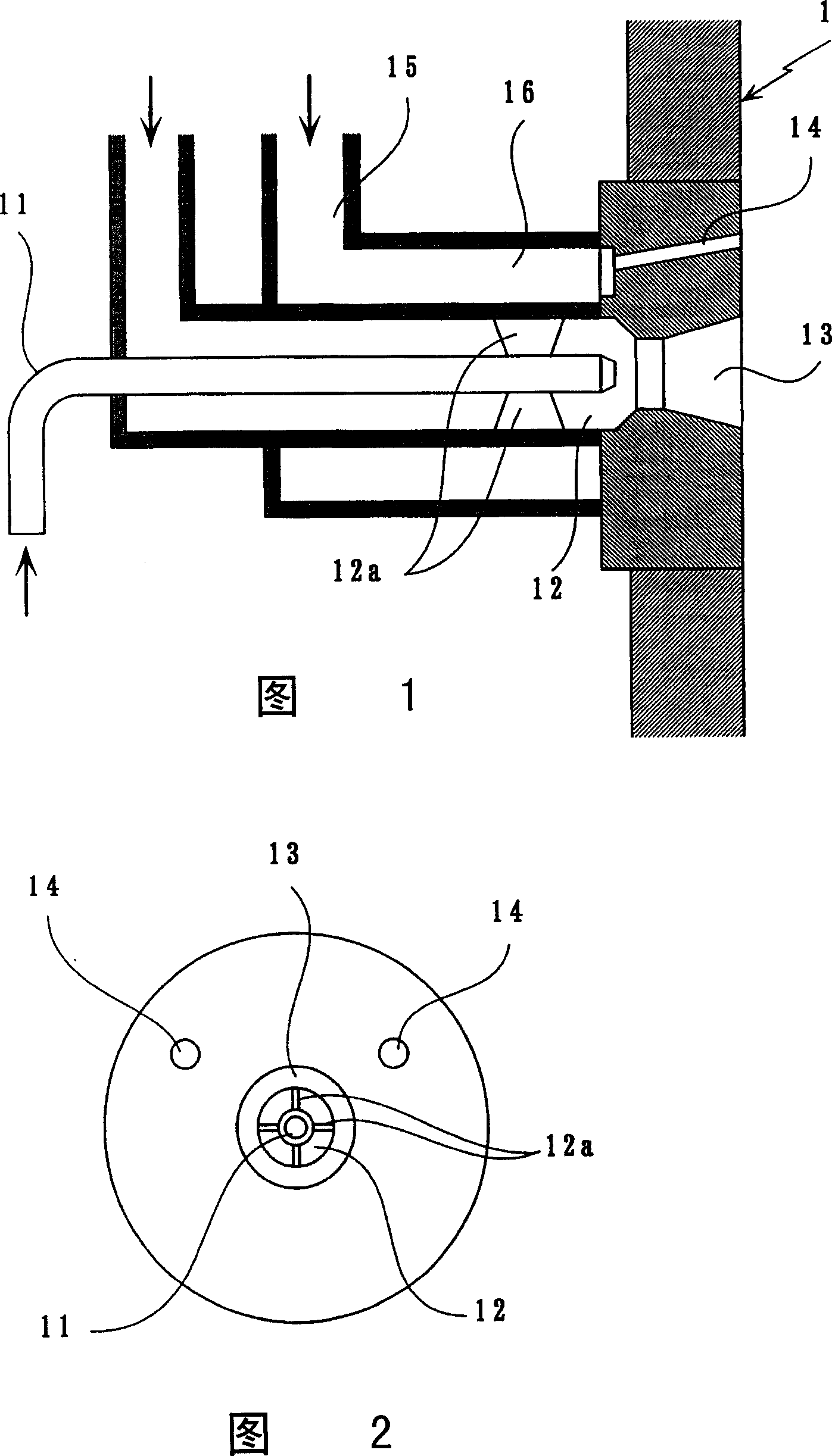
[0022] A combustion device according to embodiment 1, such as figure 1 As shown in and 2, fuel is supplied to the main combustion portion 13 via a fuel supply nozzle 11, and less than a theoretical amount of main air calculated based on the above-mentioned fuel is introduced into a main air supply nozzle 12, which Formed outside the fuel supply nozzle 11 . The swirl vanes 12a provided in the main air nozzles 12 are operable to swirlly supply the main air to the main combustion sections 13 so that the thus supplied fuel and the main air can be combusted in the main combustion sections 13. The main combustion flame is introduced into a furnace 1 .

[0023] When making less than a theoretical amount of main air and fuel burn in the main combustion section 13, the main combustion in the main combustion section 13 is incomplete, so that it is inhibited due to the temperature reduction of the main combustion flame entering the furnace 1. NOx production. By the way, the amount of ...

Embodiment 2

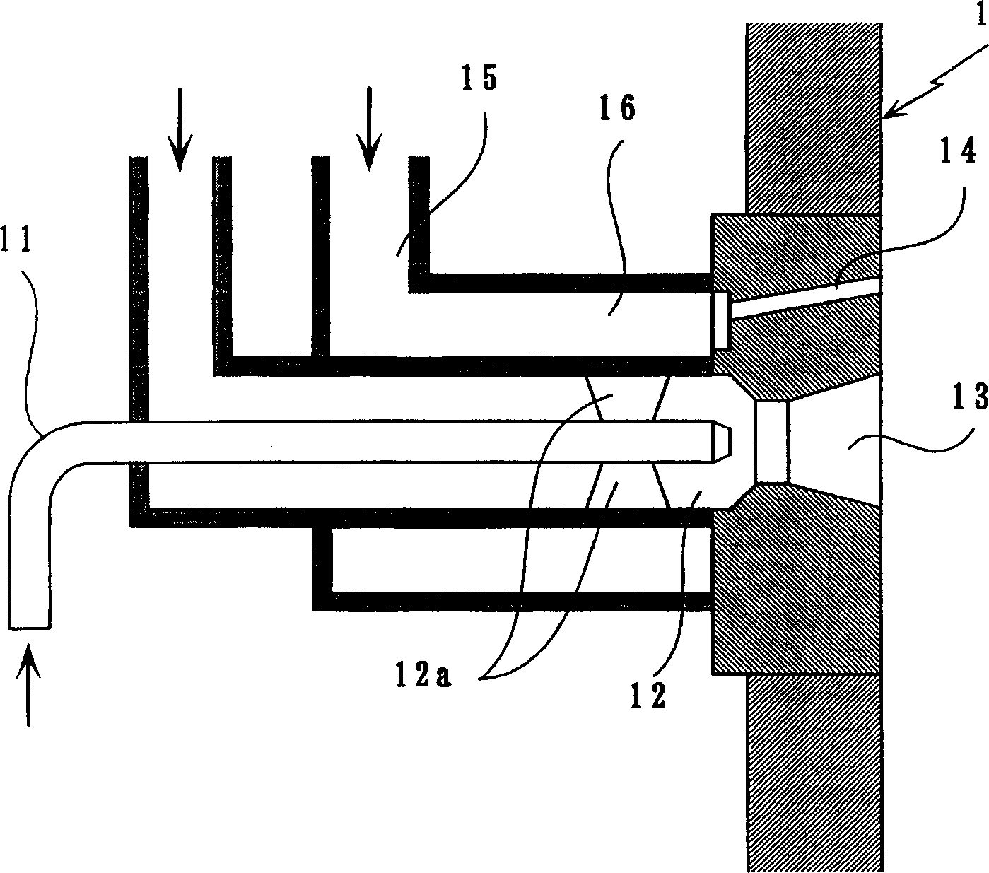
[0037] A combustion device of Embodiment 2 has the same feature as that of the foregoing Embodiment 1, that is, the fuel is supplied to the main combustion portion 13 via the fuel supply nozzle 11, and the main combustion unit will be less than the theoretical amount calculated from the above-mentioned fuel. The air is introduced into a main air supply nozzle 12 formed outside the fuel supply nozzle 11 . The swirl vanes 12a provided in the main air nozzles 12 are operable to swirlly supply the main air to the main combustion sections 13 so that the thus supplied fuel and the main air can be combusted in the main combustion sections 13. The main combustion flame is introduced into a furnace 1 .

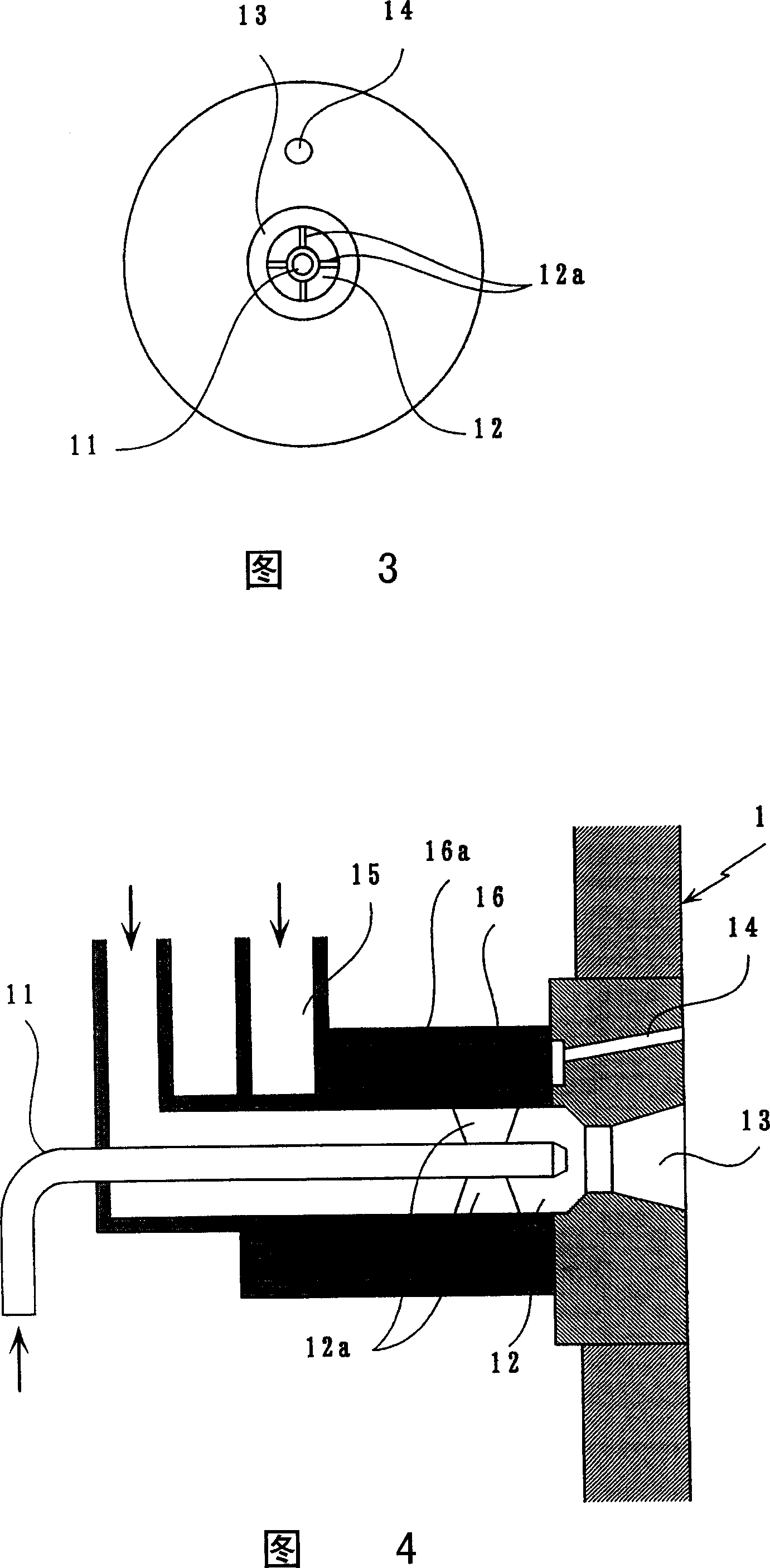
[0038] On the other hand, two auxiliary air supply nozzles 14 for supplying auxiliary air are provided outside the periphery of the above-mentioned main combustion portion 13 within an angle range of 160° relative to the center of the main combustion portion 13 . In addition, two auxi...


PUM


Abstract

A burner apparatus includes: a fuel supply nozzle for supplying a fuel; a primary-air supply nozzle (12) for supplying a less-than theoretical quantity of primary air based on the fuel supplied from the fuel supply nozzle; a primary combustion section (13) for combusting the fuel and primary air; and a secondary-air supply nozzle (14) disposed at place outside a periphery of the primary combustion section, and is characterized in that one or more of the secondary-air supply nozzles are disposed within an angular range of 160 degrees with respect to a center of the primary combustion section and are each inclined outwardly relative to the primary combustion section.

Description

technical field [0001] The present invention relates to combustion devices. More specifically, the present invention is concerned with further reducing NOx generation so that the combustion exhaust gas may contain a smaller amount of NOx, the combustion apparatus comprising: a fuel supply nozzle for supplying fuel; a main air supply nozzle for supplying less than a theoretical amount of main air calculated based on the fuel supplied from the fuel supply nozzle; a main combustion section for combusting the fuel and the main air; and, an auxiliary air supply nozzle provided at a position outside the periphery of the main combustion section and is used to supply auxiliary air. Background technique [0002] For the purpose of environmental protection, methods for reducing the amount of NOx contained in combustion exhaust gas at the time of product combustion have been conventionally studied. [0003] A method for reducing the amount of NOx in combustion exhaust gas is disclose...

Claims


Application Information

Patent Timeline
IPC IPC(8): F23C11/00F23L9/00F23C6/04F23C7/00F23C99/00F23L15/02
CPCF23C6/045F23C7/008F23C7/004F23L15/02F23C2201/20Y02E20/34
Inventor 中川博夫吉田诚治池田勇有田彩司
Owner CHUGAI RO CO LTD
Features
  • R&D
  • Intellectual Property
  • Life Sciences
  • Materials
  • Tech Scout
  • Unparalleled Data Quality
  • Higher Quality Content
  • 60% Fewer Hallucinations
Learn More