Multi-rotor synchronous machine permitting relative movement between rotors

a synchronous machine and rotor technology, applied in the direction of engine starters, magnetic circuit rotating parts, magnetic circuit shape/form/construction, etc., can solve the problems of increasing the overall length of the power train, complex structure, and excessive armature winding-induced voltage applied to semiconductor elements, etc., to achieve high reliability levels

Inactive Publication Date: 2006-02-14
DENSO CORP
View PDF25 Cites 113 Cited by
  • Summary
  • Abstract
  • Description
  • Claims
  • Application Information

AI Technical Summary

Benefits of technology

[0011]It is another object of the invention to provide a compact structure of a multi-rotor synchronous machine designed to operate selectively in a motor mode and a generator mode with high reliability levels.

Problems solved by technology

However, increasing a magnet-produced magnetic field in such a driving motor in order to ensure a sufficient torque during rotation of the motor at low speeds causes an excessive armature winding-induced voltage to be applied to semiconductor elements of a driving circuit during rotation at high speeds undesirably.
The synchronous machine, as taught in the former document, has a problem that the structure is complex.
The motor generator, as taught in the latter document, encounters drawbacks in that the mounting of the motor generator between the crankshaft and the transmission installed behind the crankshaft causes the overall length of the power train to be increased, thus resulting in increases in size and weight of an assembly of the power train and its cover and also results in a difficulty in ensuring the rigidity sufficient to resist mechanical vibrations and deformation of the power train.

Method used


Image

  • Multi-rotor synchronous machine permitting relative movement between rotors
  • Multi-rotor synchronous machine permitting relative movement between rotors
  • Multi-rotor synchronous machine permitting relative movement between rotors

Examples


first embodiment

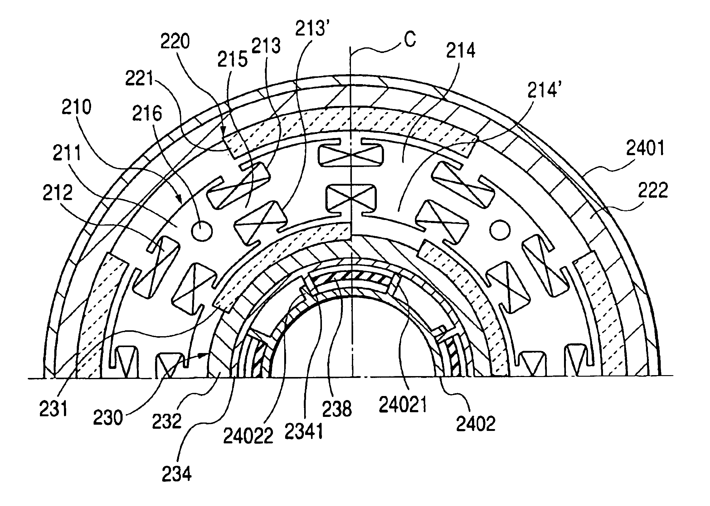
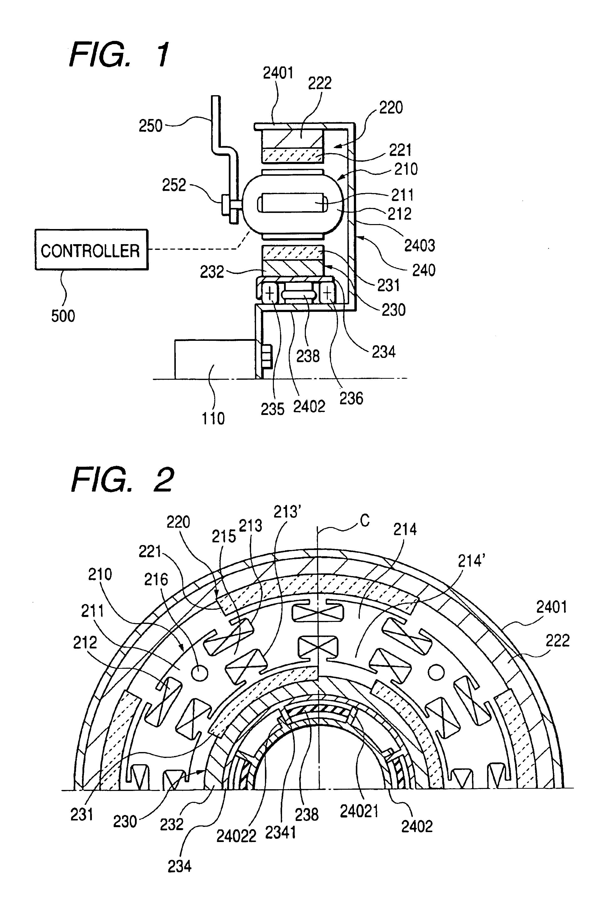
[0074]Referring to the drawings, wherein like reference numbers refer to like parts in several views, particularly to FIGS. 1 and 2, there is shown a multi-rotor synchronous machine according to the invention. The following discussion will refer to an example in which the multi-rotor synchronous machine is used as a dynamo electric machine or generator / motor for automotive vehicles such as hybrid vehicles.

[0075]The synchronous machine includes generally a stator 210, an outer rotor 220, an inner rotor 230, a rotor support frame 240, and a stator support frame 250.

[0076]The stator 210 consists of a hollow cylindrical stator core 211 disposed within an annular gap between the outer rotor 220 and the inner rotor 230 coaxially therewith and armature coils 212 magnetically coupling with the rotors 220 and 230.

[0077]The stator core 211 is made of a lamination of a plurality of magnetic discs laid to overlap each other in an axial direction of the synchronous machine. The stator core 211, ...

third embodiment

[0134]FIG. 27 shows a multi-rotor synchronous machine according to the invention. The same reference numbers as employed in the above embodiments will refer to the same parts, and explanation thereof in detail will be omitted here.

second embodiment

[0135]The multi-rotor synchronous machine of this embodiment has substantially the same structure as described in the Specifically, stator windings 212 (i.e., armature coils) are arrayed in a magnetic core 211 of a stator 210. Each stator winding 212 consists of a conductor shaped to form a number of loops or turns each of which extends from a front surface of the magnetic core 211 into one of slots 213′ perpendicular to the drawing of FIG. 27, passes over a back surface of the core back 215, enters one of slots 213, and returns back to a front surface of the magnetic core 211. The armature coils 212 arrayed at a three-slot interval away from each other are coupled to form one of three-phase windings.

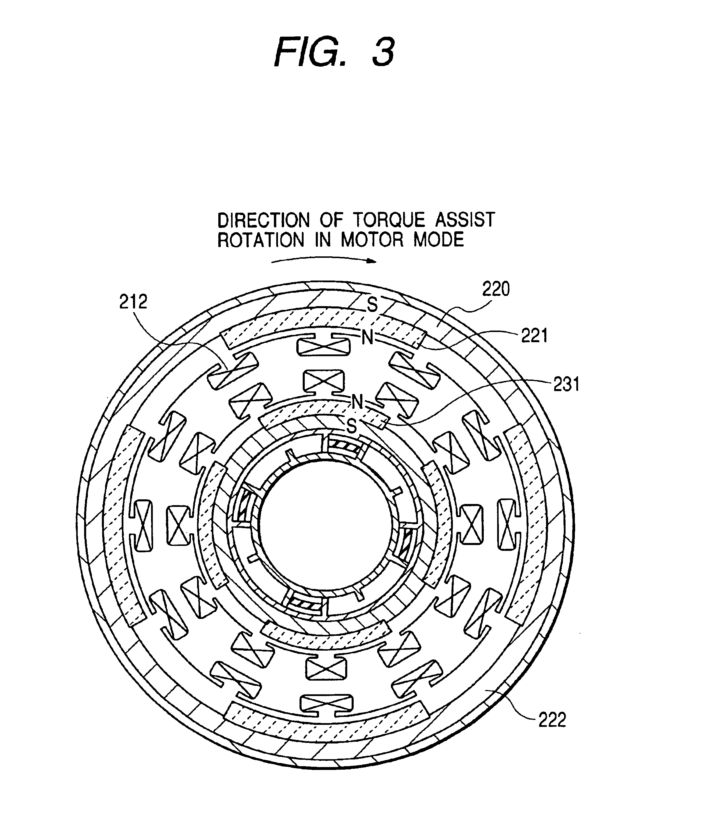
[0136]The multi-rotor synchronous machine also includes an outer rotor 220 and an inner rotor 230. Magnets 221 and 231 are secured on the outer and inner rotors 220 and 230.

[0137]A rotor support stay 240 is connected to a crankshaft 110 of the engine. A magnetic core 211 is installed o...


PUM


Abstract

A compact and reliable structure of a multi-rotor synchronous machine which may be employed as a generator / motor for automotive vehicles is provided. The machine includes an outer rotor having permanent magnets, an inner rotor having permanent magnets disposed to be rotatable relative to the outer rotor, a stator core having armature coils interlinking with field magnetic fluxes produced by the outer and inner rotors, and a rotor-to-rotor relative rotation controlling mechanism. A relative angle between the outer and inner rotors is controlled within a given angular range by controlling the phase and quantity of current flowing through the armature coils to rotate the inner rotor relative to the outer rotor through the rotor-to-rotor relative rotation controlling mechanism, thereby changing the magnetic fluxes interlinking with the armature coils as needed.

Description

[0001]This application is a divisional application of U.S. patent application Ser. No. 09 / 950,823, filed Sep. 13, 2001, now abandon which is based on and incorporates herein by reference Japanese Patent Application No. 2000-280608 filed on Sep. 14, 2000.BACKGROUND OF THE INVENTION[0002]1. Technical Field of the Invention[0003]The present invention relates generally to a multi-rotor synchronous machine which may be used as a generator / motor for automotive vehicles such as hybrid vehicles, and more particularly to a compact and reliable structure of a multi-rotor synchronous machine.[0004]2. Background Art[0005]Typical permanent magnet synchronous machines are capable of producing a higher output and have the structure easy to reduce in size as compared with other types of synchronous machines and thus suitable for use as driving motors of hybrid vehicles or electric vehicles. However, increasing a magnet-produced magnetic field in such a driving motor in order to ensure a sufficient ...

Claims


Application Information

Patent Timeline
Patent Type & Authority Patents(United States)
IPC IPC(8): H02K16/02H02K21/00H02K7/18F02N11/04H02K21/12H02K21/16H02K21/22
CPCF02N11/04H02K11/048H02K21/225H02K21/029H02K21/12H02K21/16H02K16/02F02N2300/104H02K7/18H02K11/05
Inventor SEGUCHI, MASAHIROYONEDA, SHIGENORI
Owner DENSO CORP
Why Eureka
Try Eureka