Spinous process stabilization device and method

a stabilization device and process technology, applied in the field of medical devices, can solve the problems of difficult alignment of screws, neurologic deficit or even loss of mobility, and damage to the vertebral artery in the cervical region, and achieve the effect of stabilizing a portion of the spinal column and stabilizing a portion of the spin

Inactive Publication Date: 2009-10-22
GINSBERG HOWARD JOESEPH +2
View PDF9 Cites 101 Cited by
  • Summary
  • Abstract
  • Description
  • Claims
  • Application Information

AI Technical Summary

Benefits of technology

[0013]The present invention provides a device for stabilizing a portion of a spinal column w

Problems solved by technology

Instabilities can arise due to many factors including trauma, degeneracy or metastasis which may result in pain, neurological deficit or even loss of mobility.
The angle of insertion into the pedicle is paramount to complication avoidance and even minor misalignments can lead to insult of the vertebral artery in the cervical region if the placement is too lateral.
The alignment of these screws is a difficult task due to the variability present in the transverse pedicle width throughout the vertebral column.
Improper insertion of the pedicle screws can lead to insult to the vertebral artery or intrusion into the spinal canal, leading to severe neurological deficit.
Due to the risks associated with the procedure, extreme caution is necessary for proper installation.
This has led to large surgical exposure for extended periods of time which, in turn, results in increased patient bl

Method used


Image

  • Spinous process stabilization device and method
  • Spinous process stabilization device and method
  • Spinous process stabilization device and method

Examples


Embodiment Construction

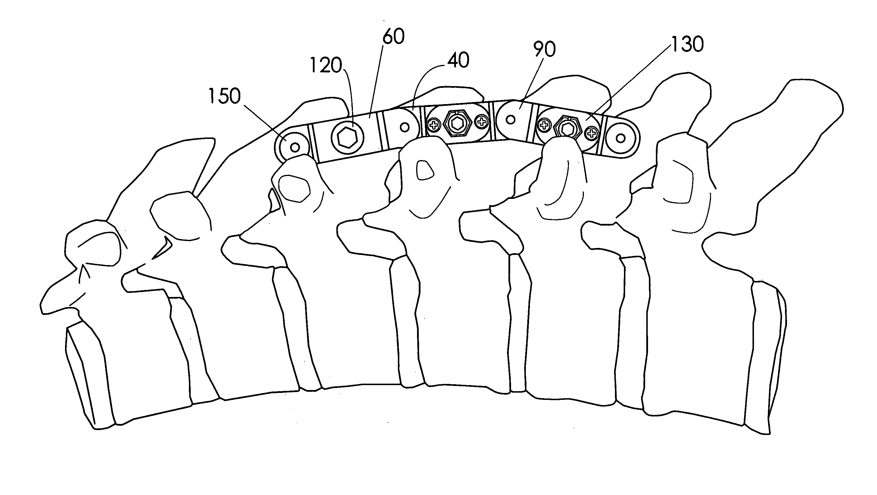
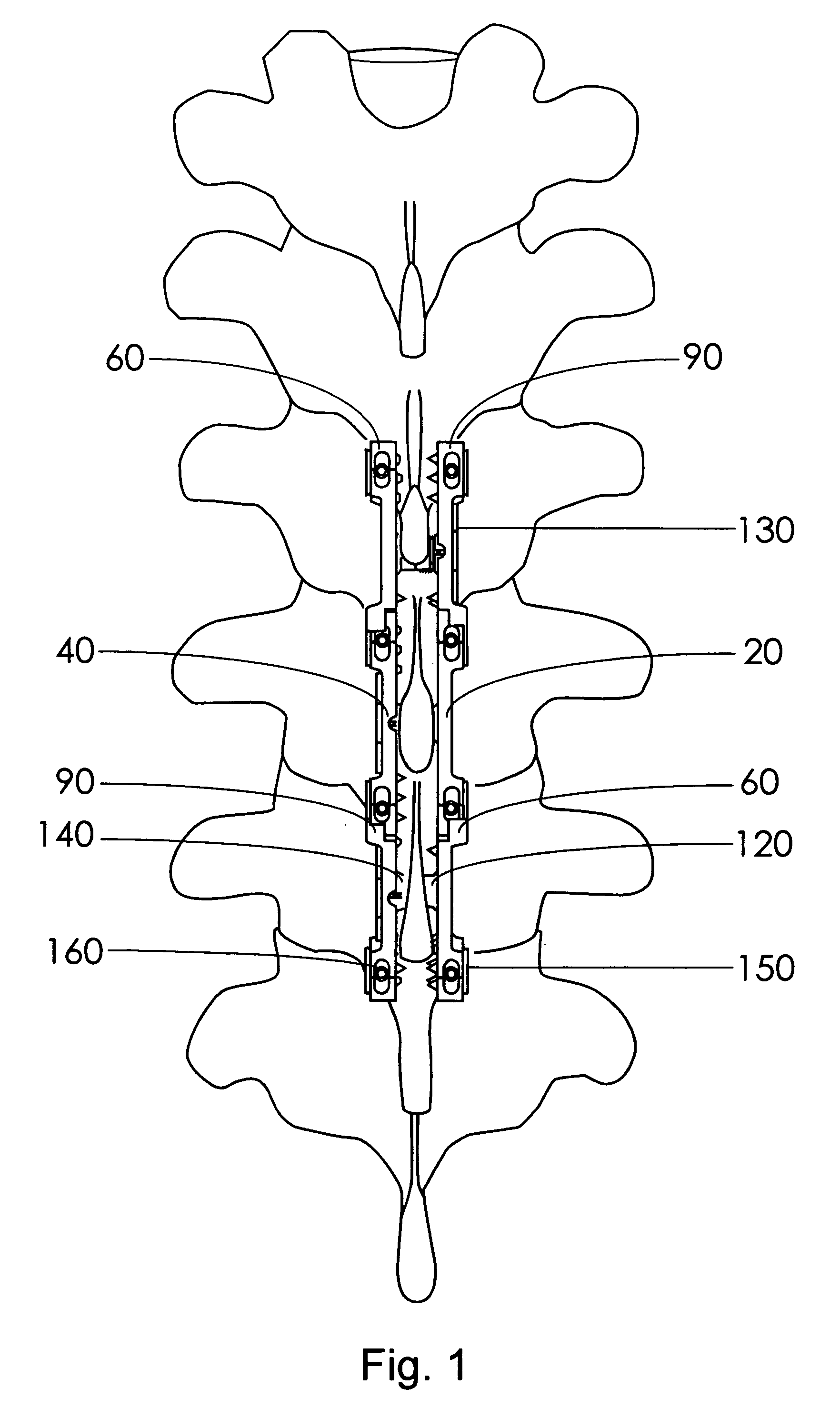
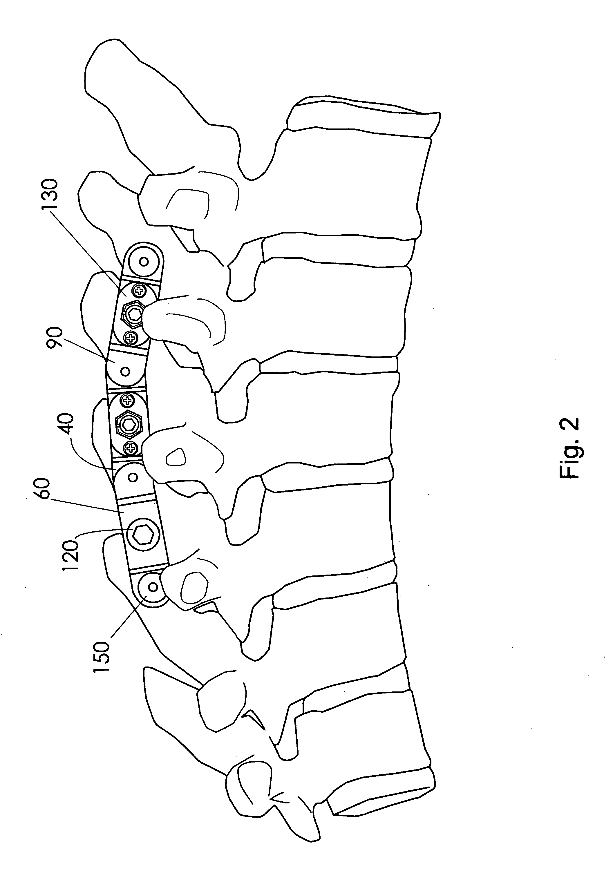
[0058]Generally speaking, the systems described herein are directed to a device and system for stabilizing a portion of a spinal column which joins together adjacent spinous processes to stabilize a portion of a spine. As required, embodiments of the present invention are disclosed herein. However, the disclosed embodiments are merely exemplary, and it should be understood that the invention may be embodied in many various and alternative forms.

[0059]The Figures are not to scale and some features may be exaggerated or minimized to show details of particular elements while related elements may have been eliminated to prevent obscuring novel aspects. Therefore, specific structural and functional details disclosed herein are not to be interpreted as limiting but merely as a basis for the claims and as a representative basis for teaching one skilled in the art to variously employ the present invention. For purposes of teaching and not limitation, the illustrated embodiments are directed...


PUM


Abstract

A fixation device to immobilize a spinal motion segment and promote posterior fusion, used as stand-alone instrumentation or as an adjunct to an anterior approach. The device functions as a multi-level fusion system including modular single-level implementations. At a single-level the implant includes a pair of plates spanning two adjacent vertebrae with embedding teeth on the medially oriented surfaces directed into the spinous processes or laminae. The complementary plates at a single-level are connected via a cross-post with a hemi-spherical base and cylindrical shaft passed through the interspinous process gap and ratcheted into an expandable collar. The expandable collar's spherical profile contained within the opposing plate allows for the ratcheting mechanism to be correctly engaged creating a uni-directional lock securing the implant to the spine when a medially directed force is applied to both complementary plates using a specially designed compression tool. The freedom of rotational motion of both the cross-post and collar enables the complementary plates to be connected at a range of angles in the axial and coronal planes accommodating varying morphologies of the posterior elements in the cervical, thoracic and lumbar spine. To achieve multi-level fusion the single-level implementation can be connected in series using an interlocking mechanism fixed by a set-screw.

Description

CROSS REFERENCE TO RELATED APPLICATION[0001]This patent application relates to, and claims the priority benefit from, U.S. Provisional Patent Application Ser. No. 61 / 071,137 filed on Apr. 14, 2008 entitled SPINOUS PROCESS STABILIZATION DEVICE AND METHOD and which is incorporated herein in its entirety.FIELD OF THE INVENTION[0002]The present invention generally relates to the field of medical devices, and, more particularly to a system for fusing the spinal column from the posterior aspect to restore stability. In the outlined embodiment, the system is comprised of a series of single level, dual-plate fusion devices which, utilizing the spinous processes and laminae of adjacent vertebral levels as the sole point of the bone-implant interface, immobilize a given spinal motion segment, thus promoting the bony fusion necessary to restore stability to a compromised spinal column.BACKGROUND OF THE INVENTION[0003]The functions of the spinal column are to provide stability and mobility, pro...

Claims


Application Information

Patent Timeline
IPC IPC(8): A61B17/70A61B17/88
CPCA61B17/7068
Inventor GINSBERG, HOWARD JOESEPHSINGH, DEVIN ANANDWHYNE, CARI MARISA
Owner GINSBERG HOWARD JOESEPH
Why Eureka
Try Eureka