Connecting structure for electric wire to shield case of apparatus

A technology for connecting structures and wires, which is applied to the parts of connecting devices, electromechanical devices, conductive connections, etc., which can solve the problems of increasing the number of parts and poor operability, so as to reduce the number of parts, reduce costs, and excellent operability Effect

Inactive Publication Date: 2004-12-01
株式会社自动车电网络技术研究所 +3
View PDF1 Cites 29 Cited by
  • Summary
  • Abstract
  • Description
  • Claims
  • Application Information

AI Technical Summary

Problems solved by technology

[0003] Meanwhile, the prior art has a shielded connector in which terminals are fixed by bolts inside the shield case and by tightening the bolts according to such a connection structure, which requires an opening portion constituting an operation port for tightening the bolts, for Close the waterproof cover of the opening part, but this increases the number of parts, and its structure is considered bad in terms of operability

Method used


Image

  • Connecting structure for electric wire to shield case of apparatus
  • Connecting structure for electric wire to shield case of apparatus
  • Connecting structure for electric wire to shield case of apparatus

Examples


Embodiment Construction

[0026] The following will refer to Figure 1 to Figure 9 Example 1 that includes the present invention is described.

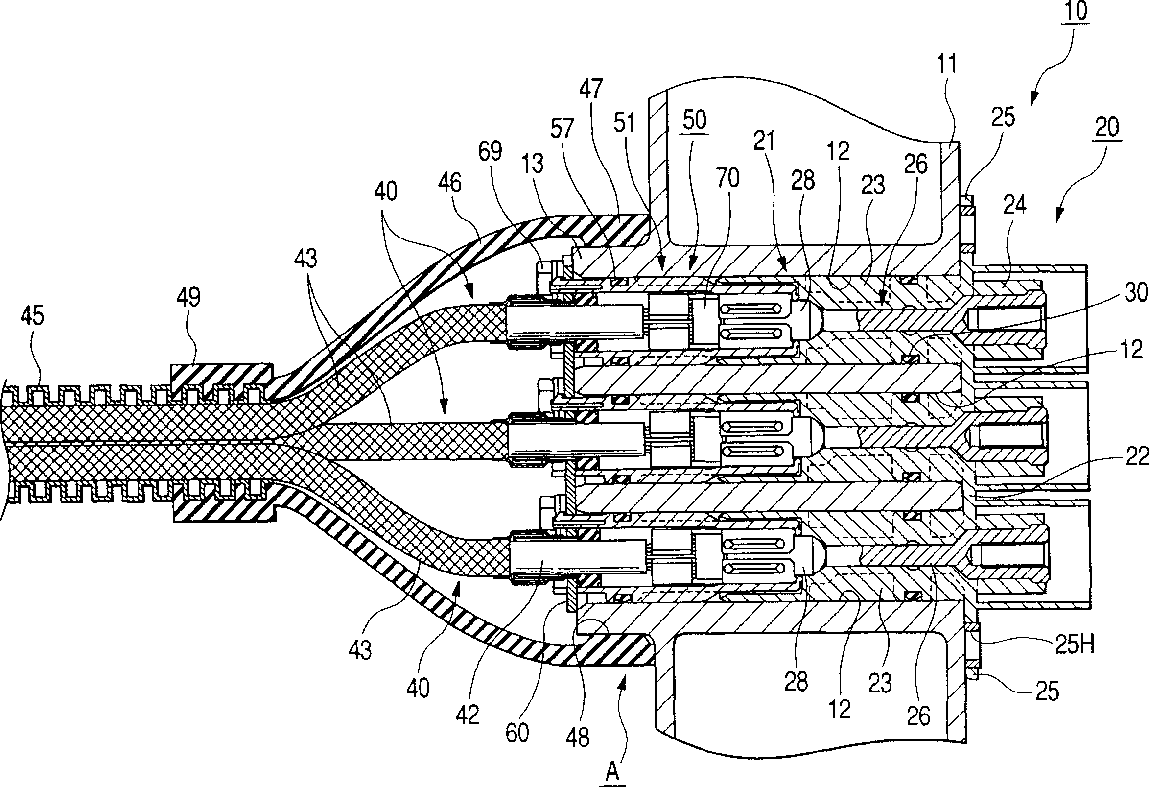
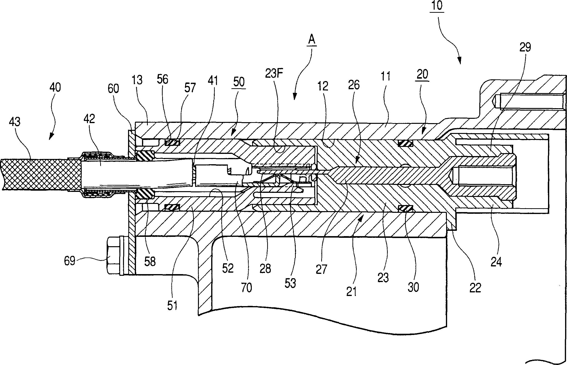
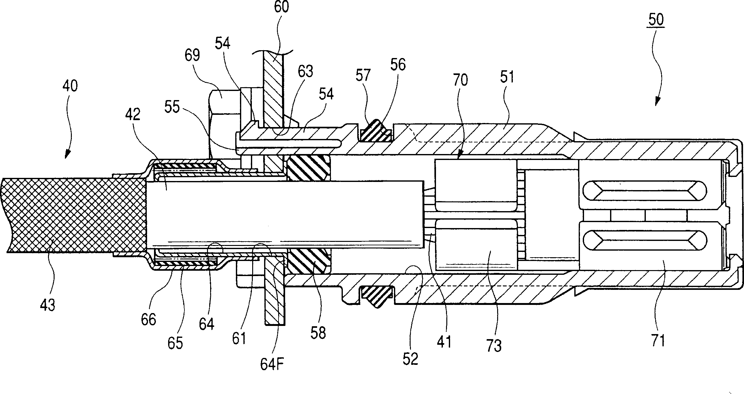
[0027] Such as figure 1 and figure 2 As shown, in the structure A of connecting electric wires to the device shield case according to the present embodiment, the electric wire side connector 50 is connected to the end portion of the conductor 41 constituting the core wire of the shielded electric wire 40, and the shield layer 43 of the shielded electric wire 40 Connected to the shield case 11 of the device 10 (such as a switching device of an electric car), the wire-side terminal 70 provided on the wire-side connector 50 is connected to the device-side terminal 26 inside the shield case 11 .

[0028] The device 10 is constituted by accommodating the device main body within the conductive shield case 11 and similarly accommodating the device-side connector 20 connected to the device main body within the shield case 11 . In the upper end portion of the side ...


PUM


Abstract

Therein is provided with a connecting structure to the shield case of an apparatus so that a number of the connector parts are decreasing and that connecting operation is facilitated. The connector includes a insulative first housing fixed in a state of being inserted into a through hole, a first terminal held by the housing to face the through hole and connected to the electric circuit. The second housing of the electric wire side is fitted to the first housing. The second terminal is connected to the first terminal. Sealing rings are provided between the outer periphery of the housings and the through hole on outer-periphery of the housings so that the bracket fixed to the shield case is electrically connected to shield layer of the shield electric wire. A connecting member electrically connects the bracket and the shield layer outside of the second housing.

Description

technical field [0001] The present invention relates to a structure for connecting electric wires to a shield case of a device. Background technique [0002] A structure is used which connects electric wires to the shield case for connecting a device such as an inverter device, a motor, or the like. There is a wire connection structure in which a wire-side terminal is fixedly connected to an end portion of a conductor of a shielded wire, the wire-side terminal is connected to a device-side terminal provided inside a shield case of a device, and the shield layer of the shielded wire is connected through a conductive connection member. to a shield case (see, for example, JP-A-2002-125348). [0003] Meanwhile, the prior art has a shielded connector in which terminals are fixed by bolts inside the shield case and by tightening the bolts according to such a connection structure, which requires an opening portion constituting an operation port for tightening the bolts, for The w...

Claims


Application Information

Patent Timeline
Patent Type & Authority Applications(China)
IPC IPC(8): H01R9/05H01R13/52H01R13/648
CPCH01R13/5208H01R9/0521H01R2201/26H01R13/6485
Inventor 宫崎正相原浩佐佐木庆
Owner 株式会社自动车电网络技术研究所
Why Eureka
Try Eureka