Network vedio monitoring system

A technology of network video surveillance and video, which is used in CCTV systems, transmission monitoring, transmission systems, etc.

Inactive Publication Date: 2005-01-05
CHINA TELECOM CORP LTD
View PDF0 Cites 29 Cited by
  • Summary
  • Abstract
  • Description
  • Claims
  • Application Information

AI Technical Summary

Problems solved by technology

Although digitalization has been initially realized, this second-generation video surveillance system is still only used as a security product

Method used


Image

  • Network vedio monitoring system
  • Network vedio monitoring system
  • Network vedio monitoring system

Examples


Embodiment Construction

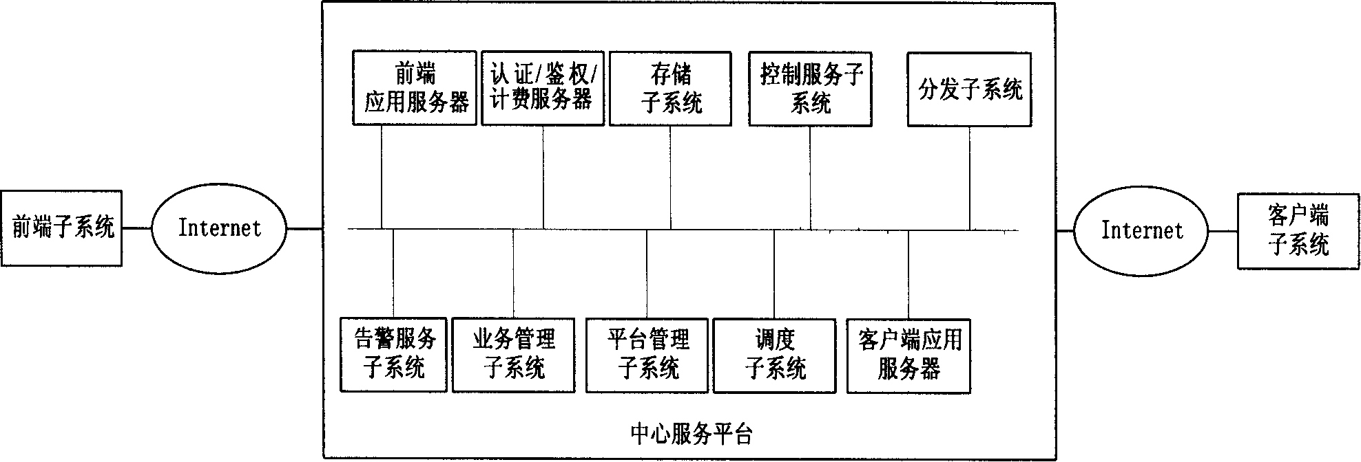
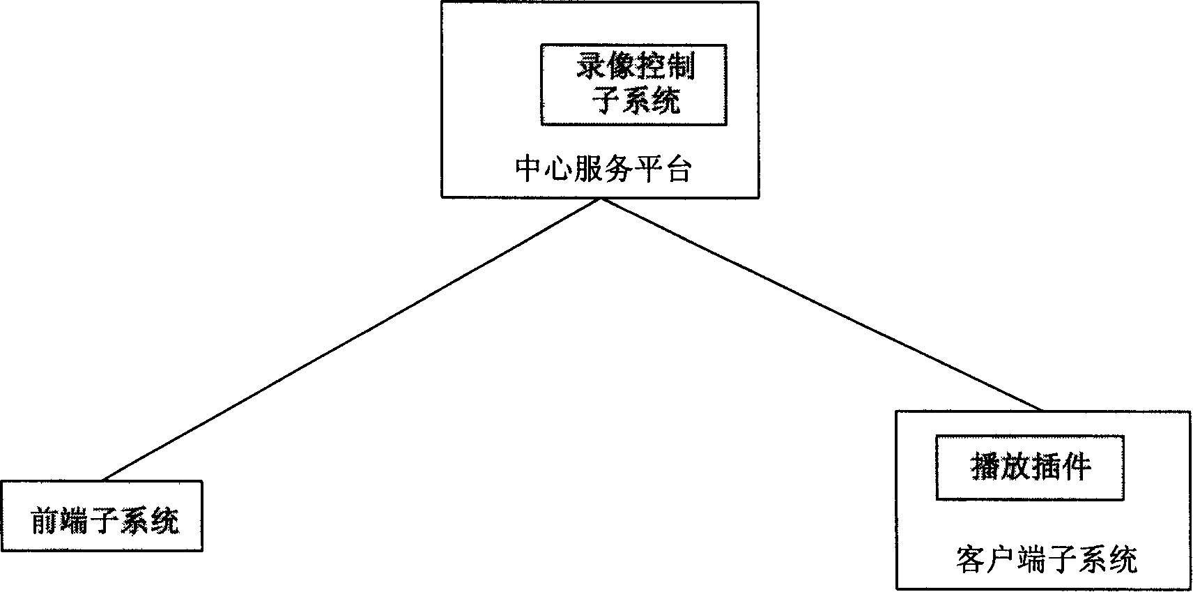
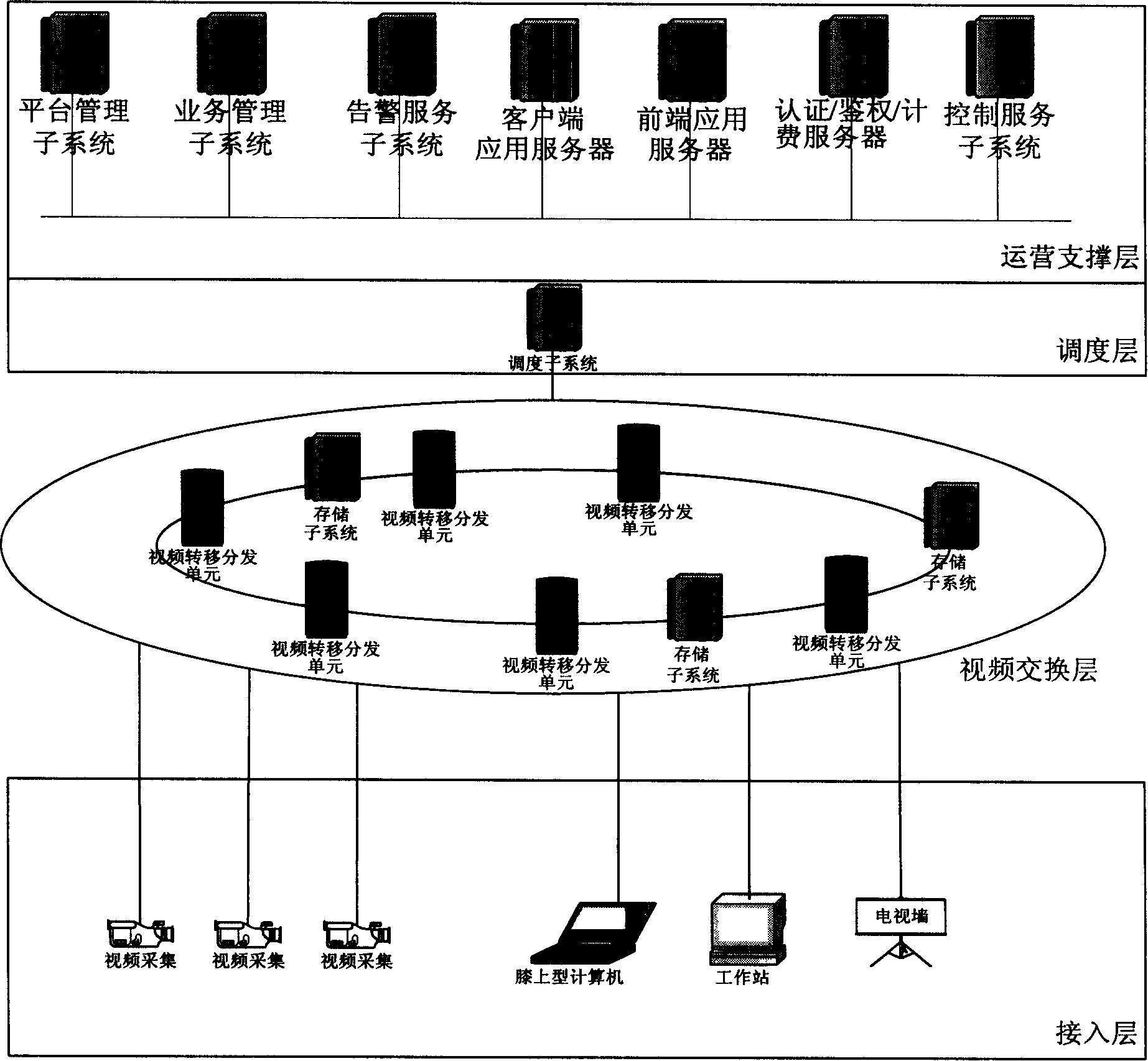
[0028] figure 1 It is the physical architecture diagram of the network video surveillance system. The network video surveillance system includes a front-end subsystem, a client subsystem and a central service platform.

[0029] The front-end subsystem is a subsystem composed of all equipment used for audio and video information, alarm information, control information acquisition, buffering, encoding, forwarding, and possible storage. It includes: camera, PTZ, video server, alarm input and output devices, and local digital video recorder (DVR), etc. The important alarm information mainly comes from the alarm of the I / O serial port and the alarm generated by the video server based on image motion detection.

[0030] The client subsystem is a device used to browse and control remote video and systems. Including real-time and historical audio and video decoding and playback, user management interface, service opening and management interface, system maintenance interface, alarm...


PUM


Abstract

This invention relates to a third generation network video monitor system which interconnects the front subsystem, the customer end subsystem and a central service plat form by the IP loading network, among which, the central service platform is composed of the national management center, the provincial/regional management center and the local center. The telecommunication service merchants provide network video monitor safety and warning service to the public.

Description

technical field [0001] The present invention generally relates to a video surveillance system, and in particular to a third-generation network video surveillance system based on embedded technology and based on network and communication technologies. Background technique [0002] The development of my country's network video surveillance technology has gone through the following three stages: [0003] 1. Early closed-circuit video surveillance system. It evolved from security products and is the first generation of analog video surveillance system in my country. [0004] 2. The PC-based plug-in video surveillance system began in the mid-1990s. Although digitalization has been initially realized, the second-generation video surveillance system is still only used as a security product for daily monitoring in certain industries due to technical deficiencies such as image quality, stability, and remote transmission monitoring. [0005] 3. The network video surveillance system...

Claims


Application Information

Patent Timeline
IPC IPC(8): H04L12/26H04N7/18
Inventor 范军蔡逆水雍丽苹冯明王志恒梁笃国郑泽民刘玮曹宁
Owner CHINA TELECOM CORP LTD
Why Eureka
Try Eureka