

Backlight assembly
A technology for backlight assembly and light source, applied in optics, diffusing elements, nonlinear optics, etc., can solve the problems of increasing the volume of the backlight assembly 10 assembly difficulty, product competitiveness slippage, light source energy loss, etc., to simplify the assembly process. and cost, enhance competitiveness, and reduce the effect of product volume
- Summary
- Abstract
- Description
- Claims
- Application Information
AI Technical Summary
Problems solved by technology
Method used
Image

Examples
Embodiment Construction
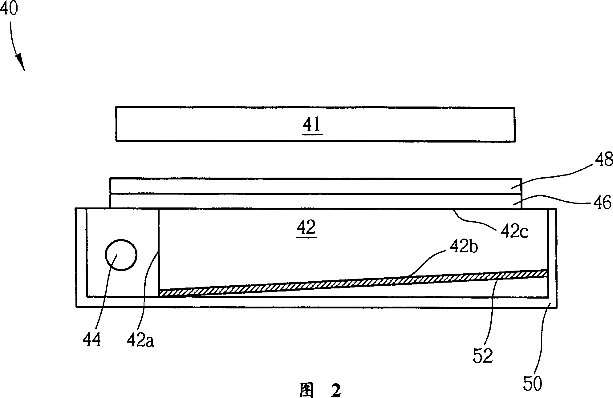
[0028] Referring to FIG. 2 , FIG. 2 is a schematic cross-sectional view of an edge light (edge light) backlight unit (BLU) 40 of the present invention. As shown in FIG. 2 , the backlight assembly 40 is disposed under a display panel (displaypanel) 41, and the backlight assembly 40 includes: a light guide plate (LGP) 42, a first side surface of the light guide plate 42 A light source generator (light source generator) 44 of 42a, a diffusing plate (diffusing plate) 46 located above the light guide plate 42, at least one prism (prism) 48 located on the surface of the diffusing plate 46, and a diffuser plate (prism) 48 located on the light guide plate 42 and covers the housing 50 around the light guide plate 42 and the light source generator 44 .
[0029] The light source generator 44 is generally a lamp tube used to provide a light source, and the light guide plate 42 includes a bottom surface (bottom surface) 42b coated on the light guide plate 42 for upward reflection (reflec...
PUM
 Abstract
Description
Claims
Application Information