RF power amplifier circuit

A power amplifier and comparator circuit technology, applied in power amplifiers, amplifier protection circuit layout, amplifiers, etc., can solve problems that cannot be used to determine the power transistor voltage of a power amplifier

Inactive Publication Date: 2005-01-26
AMPLEON NETHERLANDS
View PDF3 Cites 14 Cited by
  • Summary
  • Abstract
  • Description
  • Claims
  • Application Information

AI Technical Summary

Problems solved by technology

Therefore, under certain mismatch conditions, the signal from the coupler cannot be used to

Method used


Image

  • RF power amplifier circuit
  • RF power amplifier circuit
  • RF power amplifier circuit

Examples


Embodiment Construction

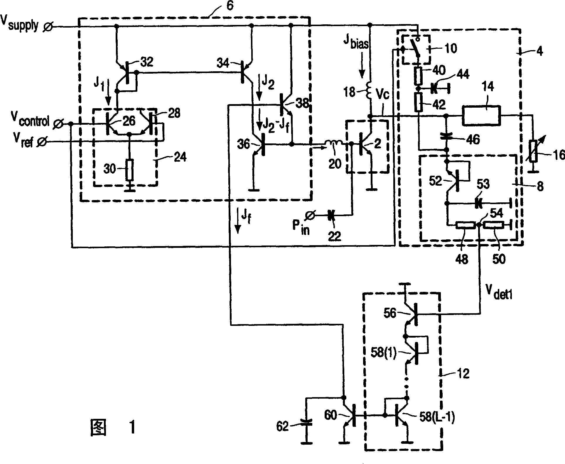
[0035]The RF power amplifier circuit of FIG. 1 has a power transistor 2 and a protection circuit 4 that protects the power transistor 2 from high voltages that cause destructive damage to the power transistor 2 . The power transistor 2 is biased by a bias circuit 6 that biases the power transistor 2 . The protection circuit 4 includes a peak detector 8 and a switch 10 that measure the output voltage of the power transistor 2 . The control circuit 12 connected to the peak detector 8 is designed to reduce the base current of the power transistor 2 when controlled by the peak detector 8 . The output of the output stage is fed through a matching circuit to a load 16, ie an antenna. The load is typically 50 ohms and it is the purpose of the protection circuit 4 to protect the power transistor 2 from damage if the load is changed and a mismatch beyond a certain value is thereby created.

[0036] The collector of the power transistor 2 is connected to the supply voltage Vsupply thr...


PUM


Abstract

A RF power amplifier circuit has at least one power transistor and a protection circuit protecting the power transistor against high voltages that lead to a destructive breakdown of the transistor. The circuit comprises a power transistor (2), a biasing circuit (6) biasing the power transistor; a peak detector (8) measuring the output voltage of the power transistor; and a comparator circuit (12) connected to the peak detector (8) and designed to reduce the base current of the power transistor (2) when controlled by the peak detector (8).

Description

technical field [0001] The present invention relates to an RF power amplifier circuit having at least one power transistor and a protection circuit that protects the power transistor from high voltages that cause destructive damage to the transistor. Such RF power amplifier circuits are used in mobile communication technology and are connected eg to the antenna of a mobile phone. [0002] The invention further relates to a wireless communication device comprising an RF power amplifier. Background technique [0003] JP 3228409 A discloses a high-frequency power amplifier in which the bias voltage of a regulator element of the power amplifier circuit is controlled as a result of detecting the electrical supply voltage of the power amplifier. By measuring the voltage of the power supply, only indirect information about the voltage at the semiconductor elements of the power amplifier can be obtained. Therefore, the protection of the semiconductor components of the power amplif...

Claims


Application Information

Patent Timeline
IPC IPC(8): H03F1/30H03F1/52H03F3/24H04B1/04
CPCH03F1/302H03F1/52H03F1/30
Inventor D·P·普里克霍德科A·G·W·P·范祖伦N·克拉梅
Owner AMPLEON NETHERLANDS
Why Eureka
Try Eureka