Cleaner having brush height control apparatus

A technology of vacuum cleaners and brushes, which is applied in the direction of vacuum cleaners, cleaning equipment, suction nozzles, etc., and can solve problems such as the increase of the gap between the suction head 102 and the floor, damage to suction and dust collection performance, etc.

Inactive Publication Date: 2005-02-02
LG ELECTRONICS INC
View PDF0 Cites 4 Cited by
  • Summary
  • Abstract
  • Description
  • Claims
  • Application Information

AI Technical Summary

Problems solved by technology

[0010] However, in the conventional vacuum cleaner described above, when in the floor cleaning mode, since the cleaning head 102 is lifted up as a whole so that the brush 109 does not come into contact with the floor, the gap between the cleaning head 102 and the floor becomes large.
This destroys the suction and dust collection performance

Method used


Image

  • Cleaner having brush height control apparatus
  • Cleaner having brush height control apparatus
  • Cleaner having brush height control apparatus

Examples


Embodiment Construction

[0031] Reference will now be made in detail to the preferred embodiments of the invention, examples of which are illustrated in the accompanying drawings.

[0032] There are several possible embodiments of the vacuum cleaner suction device according to the invention, the most preferred one being described below.

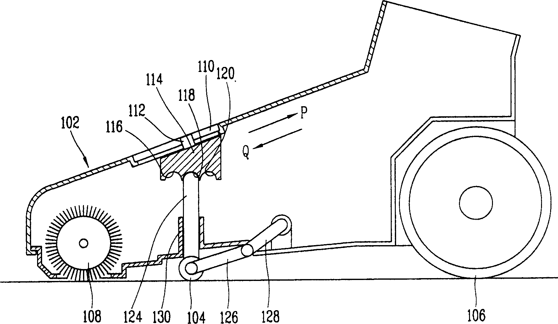
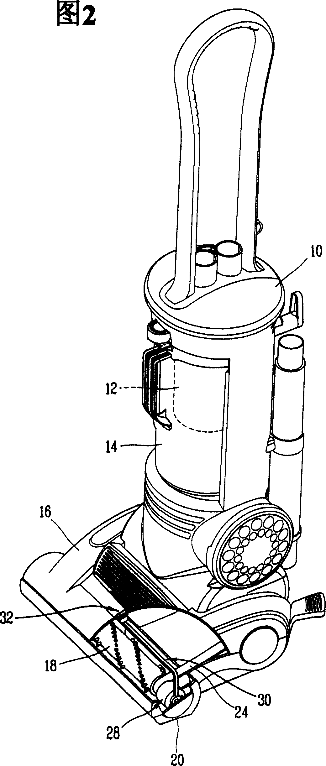
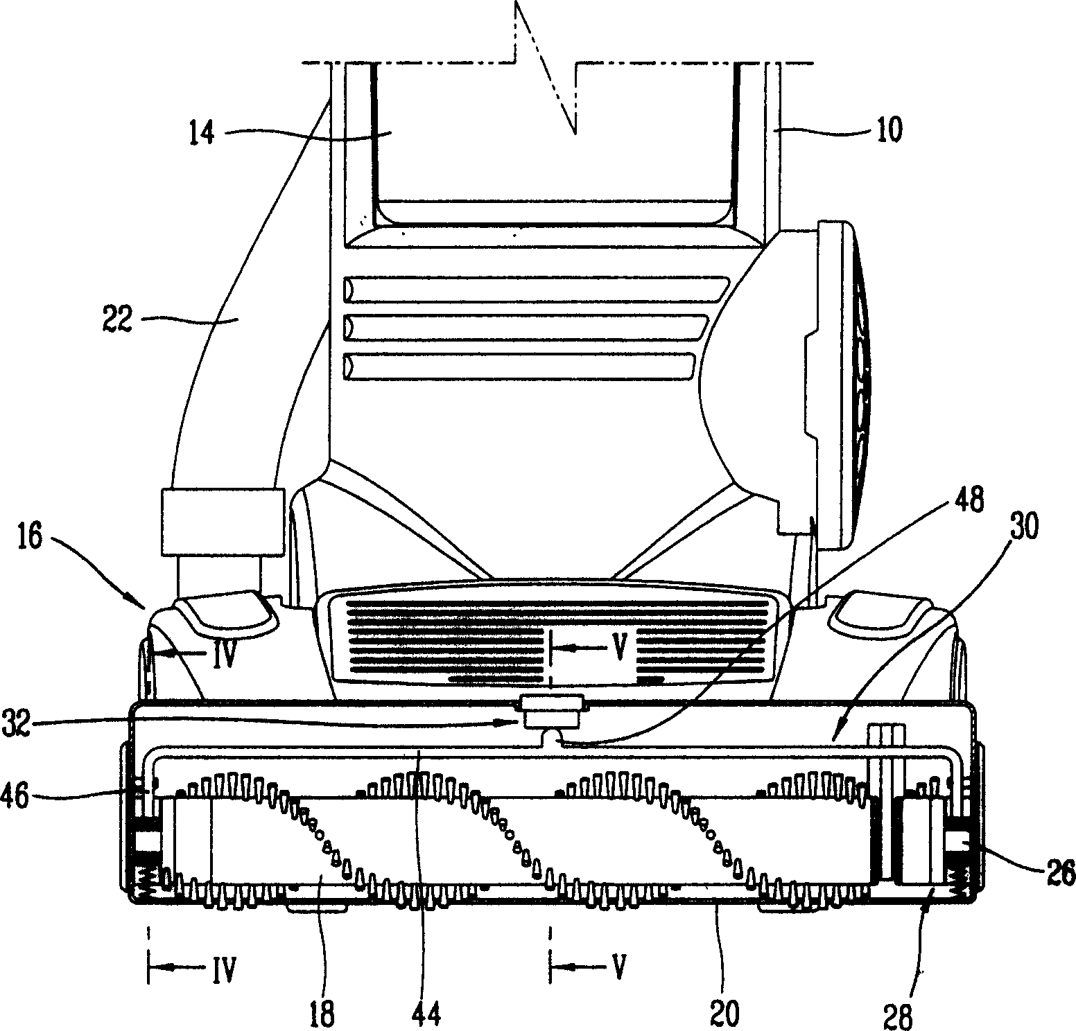
[0033] Figure 2 is a perspective view of a vacuum cleaner according to one embodiment of the present invention, image 3 is a sectional view of a vacuum cleaner according to the present invention.

[0034] The vacuum cleaner according to the present invention comprises a vacuum cleaner main body 10 in a vertical upright state; a dust suction motor (not shown) installed in the vacuum cleaner main body 10 to generate suction; A filter 12 for the dust or dirt sucked by the generated suction; a filter container 14 in which the filter 12 is installed; a dust suction head 16 placed on the lower part of the vacuum cleaner main body 10 to suck the dust and dirt on the floor...


PUM


Abstract

A cleaner includes a suction motor mounted in a cleaner main body, and generating a suction force; a filter for collecting dust or filth sucked by the suction force generated at the suction motor; a suction head connected with the filter by a suction tube, and sucking dust and filth on a floor; a brush installed in the suction head so as to ascend / descend in a vertical direction, and sweeping dust and foreign substances into the suction head; and a brush height control apparatus installed in the suction head, and making the brush ascend / descend in a vertical direction. The cleaner having a brush height control apparatus can prevent deterioration of a suction force and improving cleaning performance by constantly maintaining a gap between the suction head and the floor.

Description

technical field [0001] The present invention relates to a vacuum cleaner having a brush height control device, and more particularly, to a vacuum cleaner capable of vacuuming floors and carpets by controlling the height of the brushes. Background technique [0002] Generally speaking, a vacuum cleaner includes a dust suction motor installed in the main body to generate suction; a filter placed on the dust suction part of the dust suction motor to collect dust or dirt sucked by the suction generated by the dust suction motor; The lower suction head that sucks up dust or dirt on the floor. [0003] figure 1 is a partial sectional view showing a vacuum cleaner head according to the conventional art. [0004] In the traditional dust suction head 102, including the support wheel 104 and the drive wheel 106 installed in the bottom of the dust suction head 102, rotatably installed in the inside of the dust suction head 102, the brush 108 for cleaning dust and dirt on the floor; a...

Claims


Application Information

Patent Timeline
Patent Type & Authority Applications(China)
IPC IPC(8): A47L9/00A47L5/34A47L9/04
CPCA47L9/0494A47L5/34A47L9/00
Inventor 南贤植李映佑柳湖善郑春勉
Owner LG ELECTRONICS INC
Why Eureka
Try Eureka