Movable electric tool

A power tool and mobile technology, applied in the field of mobile power tools, can solve the problems of reduced assembly, looseness, and increased number of parts

Active Publication Date: 2005-02-09
MATSUSHITA ELECTRIC WORKS LTD
View PDF1 Cites 13 Cited by
  • Summary
  • Abstract
  • Description
  • Claims
  • Application Information

AI Technical Summary

Problems solved by technology

[0004] However, as mentioned above, in the scheme of screwing the housing 104 into the main body shell 105, in order to form a good assembly, it is necessary to ensure a gap between the male thread part and the female thread part of the screw-in part. , the gap becomes the cause of looseness
In order to prevent looseness, it is conceivable to engage multiple racks around the entire circumference of the case 104, but in this case, the overall shape will be enlarged, the number of parts will increase, and the assemblability will decrease.

Method used


Image

  • Movable electric tool
  • Movable electric tool
  • Movable electric tool

Examples


Embodiment Construction

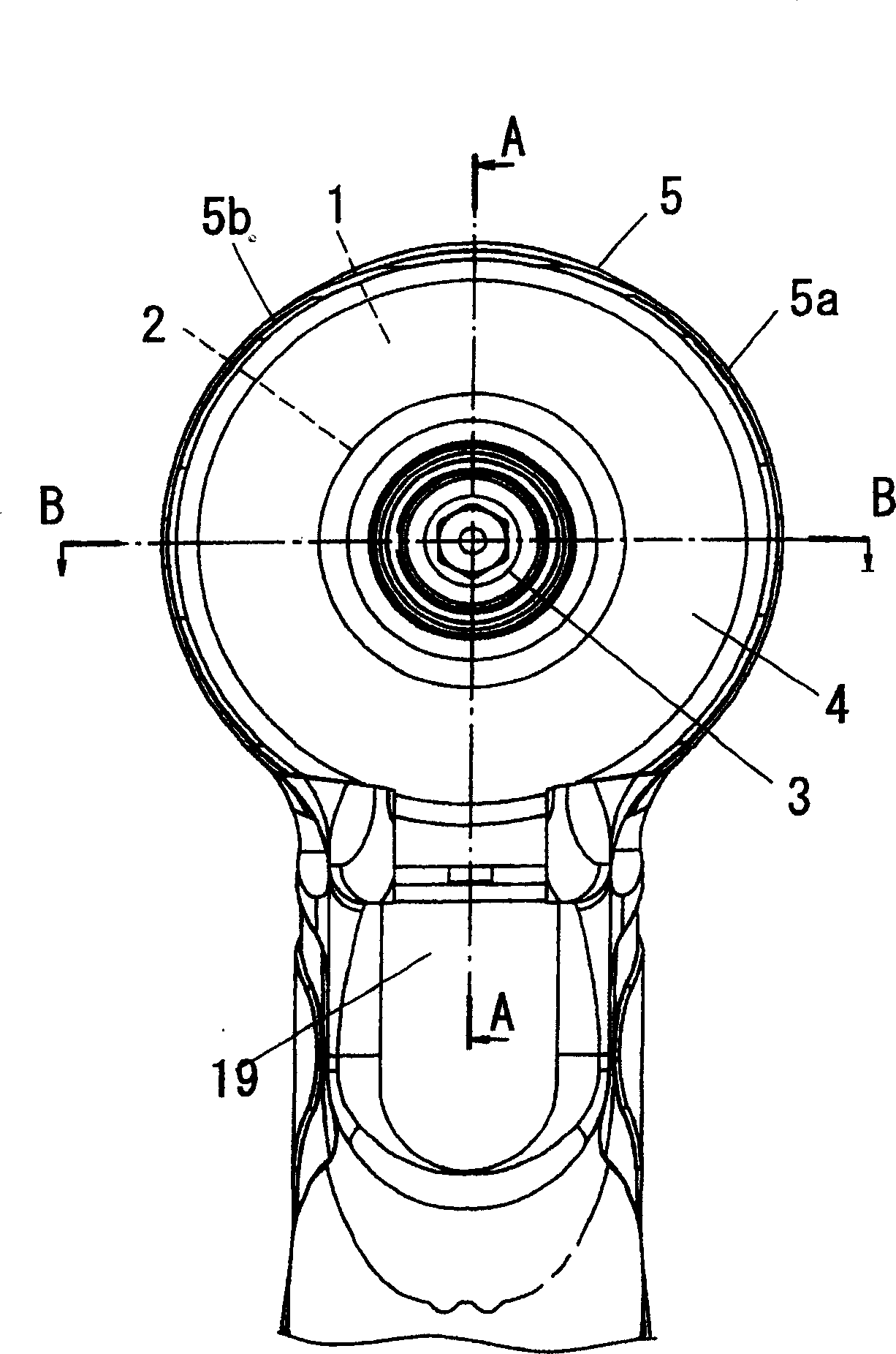
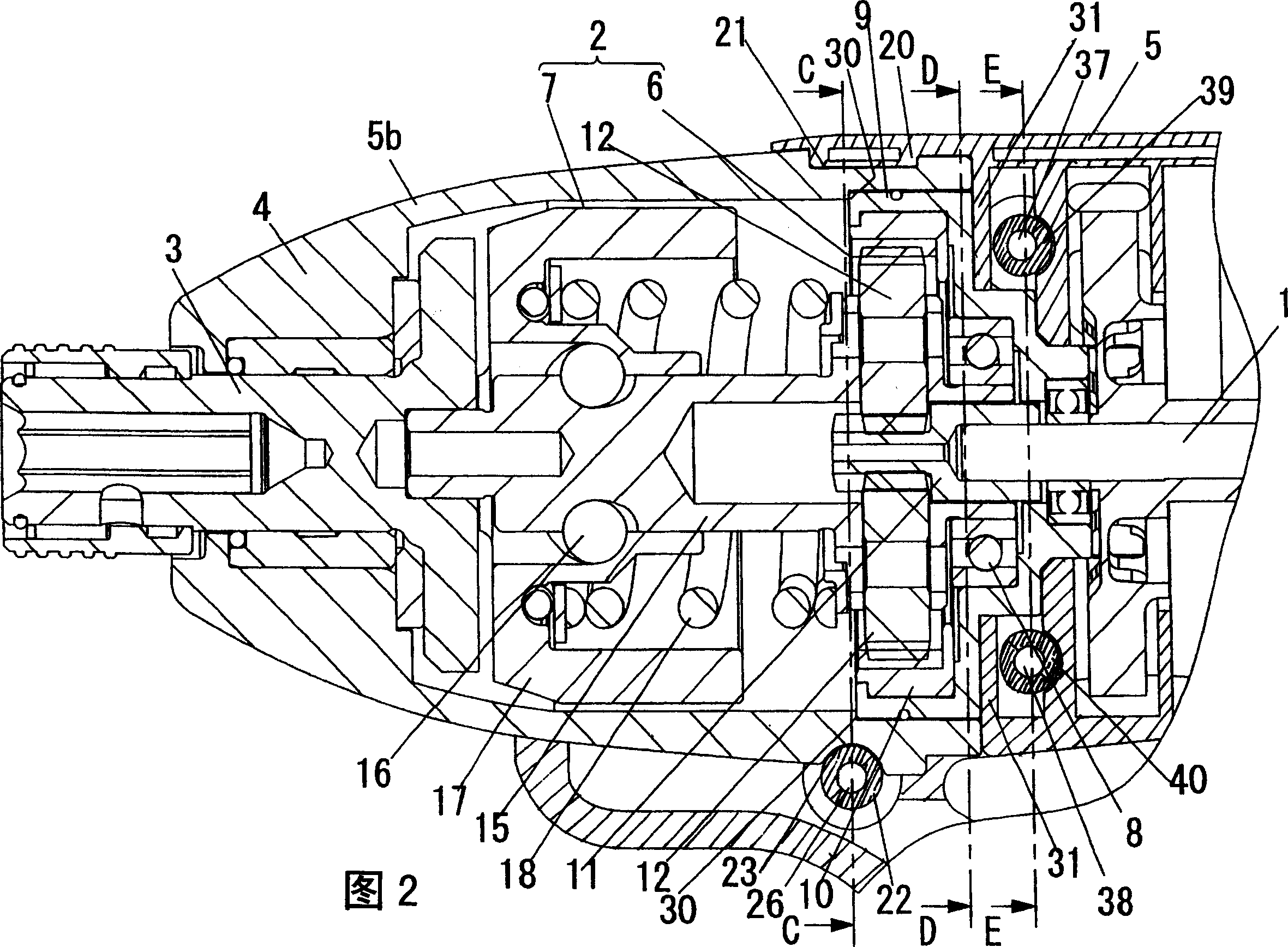
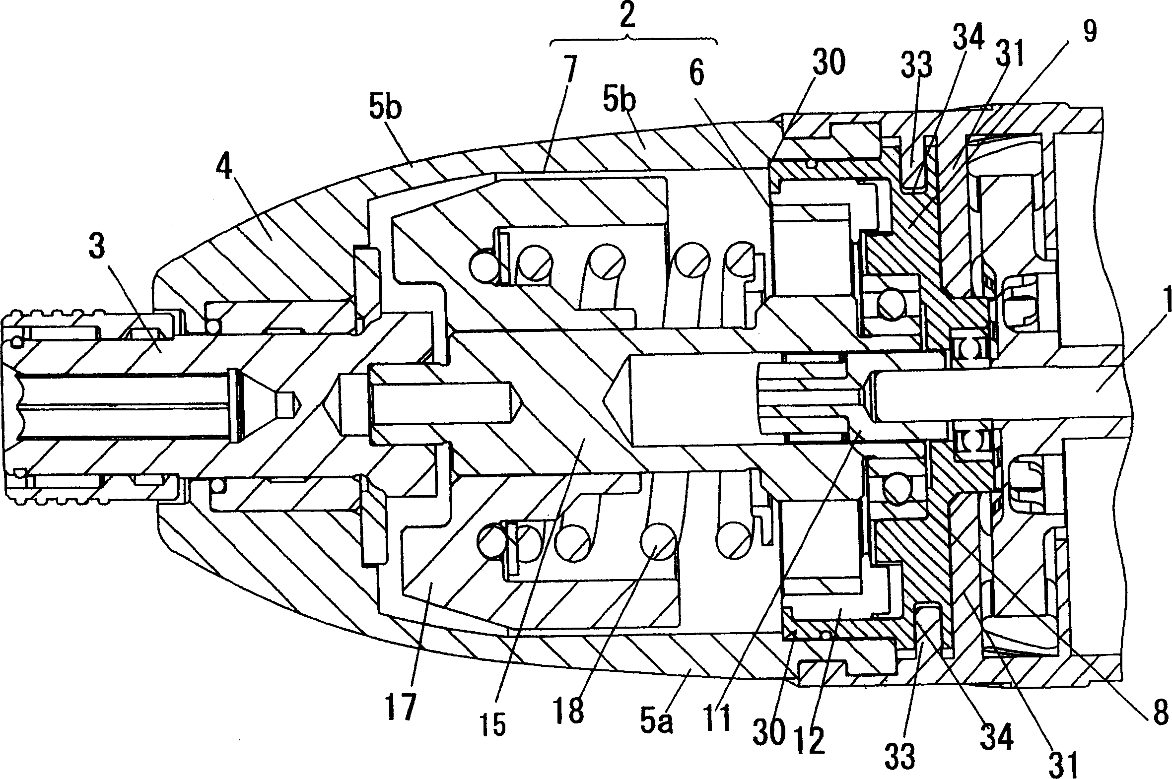
[0021] Embodiments of the present invention will be described below with reference to the accompanying drawings. figure 1 Represent the front of the mobile electric tool of an embodiment of the present invention, Fig. 2, image 3 Respectively figure 1 The A-A line profile and figure 1 The B-B line profile. The mobile electric tool is a hand-held impact screwdriver, which includes a drive motor 1; a drive transmission part 2, one end side of the drive transmission part 2 is connected to the motor 1, and the driving force of the motor 1 is transmitted to the other end side; Shaft 3, the output shaft 3 is connected to the other end side of the drive transmission part 2, and the driving force is transmitted from the drive transmission part 2; a mounting table 9, which supports the end of the drive transmission part 2 on the motor 1 side; a main body casing 5. The main body casing 5 covers the motor 1, the mounting table 9 and a part of the drive transmission part 2; the cyli...


PUM


Abstract

The present invention provides a mobile power tool which is compact and has high reliability. This mobile power tool is provided with a motor 1, a driving transmission section 2 for transmitting the driving power of the motor 1 to the output section 3, a mounting rack for supporting the driving transmission section 2, a body housing 5 for covering the motor 1 and maintaining the mounting rack, and a tubular cover 4 for covering and rotatablely supporting the output section 3. Furthermore, by fitting the body housing 5 and the driving section cover 4 so that the internal space of the two can communicate in the mobile power tool, wherein the body housing 5 is provided with an advance or retreat engaging section of the driving section cover for constraining the advance or retreat movement of the driving section cover 4 by being engaged with the driving section cover 4, and a rotational engaging section of the diving section cover for constraining the rotational movement of the driving section cover 4 by being engaged with the driving section cover 4.

Description

technical field [0001] The present invention relates to a mobile electric tool used for various fastening work, drilling work, cutting work and the like. Background technique [0002] Figure 9 Indicates the mobile power tools of the past. The mobile power tool is, for example, a hand-held impact screwdriver, such as Figure 10 As shown, a drive motor 101 is provided inside it; a drive transmission part 102, the drive transmission part 102 is connected with the motor 101 to transmit the driving force of the motor 101; an output shaft 103, the output shaft 103 is connected with the drive transmission part 102, The drive force is transmitted from the drive transmission part 102 ; and the mount 109 supports the end of the drive transmission part 102 on the motor 101 side. In this electric tool, a cylindrical metal case 104 constitutes a housing for supporting the output shaft 103 or the drive transmission part 102 so as to resist a large load generated by the drive transmissi...

Claims


Application Information

Patent Timeline
IPC IPC(8): B25F5/02B25B21/02B25B23/00B25D11/00B25D17/00B25F5/00
CPCB25F5/02
Inventor 清水秀规白谷真英
Owner MATSUSHITA ELECTRIC WORKS LTD
Why Eureka
Try Eureka