

Trolley controller
A technology for control devices and trams, applied in the direction of control drives, electric vehicles, output power conversion devices, etc., can solve problems such as system failures, and achieve the effect of miniaturization
- Summary
- Abstract
- Description
- Claims
- Application Information
AI Technical Summary
Problems solved by technology
Method used
Image

Examples
no. 1 Embodiment approach
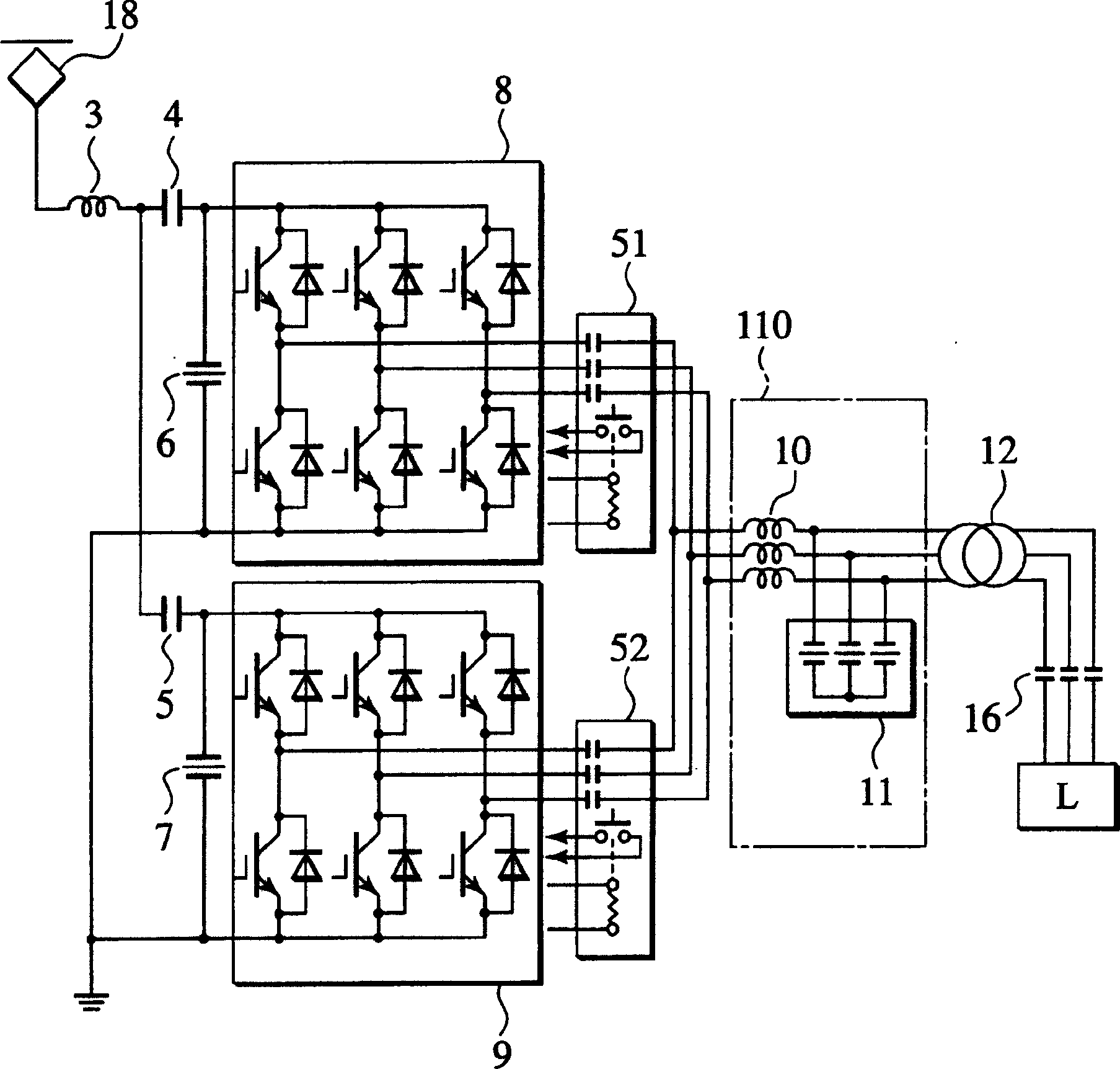
[0024] An electric train control device according to a first embodiment of the present invention will be described in detail with reference to the drawings. figure 1 It is a structural diagram of the constant-voltage constant-frequency inverter according to the first embodiment of the present invention. exist figure 1 In pair with Figure 10 Components that are structurally the same as those described in , are assigned the same symbols and descriptions thereof are omitted.
[0025] In the electric train control device according to the first embodiment of the present invention, an open switch 51 and an open switch 52 are provided on the AC side of the inverter circuit 8 and the inverter 9 . Between the open switch 51 and the open switch 52 and the AC load L, the reactor 10 , the capacitor 11 and the transformer 12 are provided.
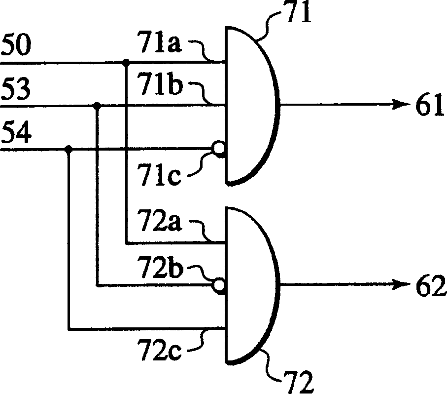
[0026] like figure 2 As shown, the auxiliary contact signal 53 and the auxiliary contact signal 54 of the open switch 51 and the open switch 52 ...
no. 2 Embodiment approach
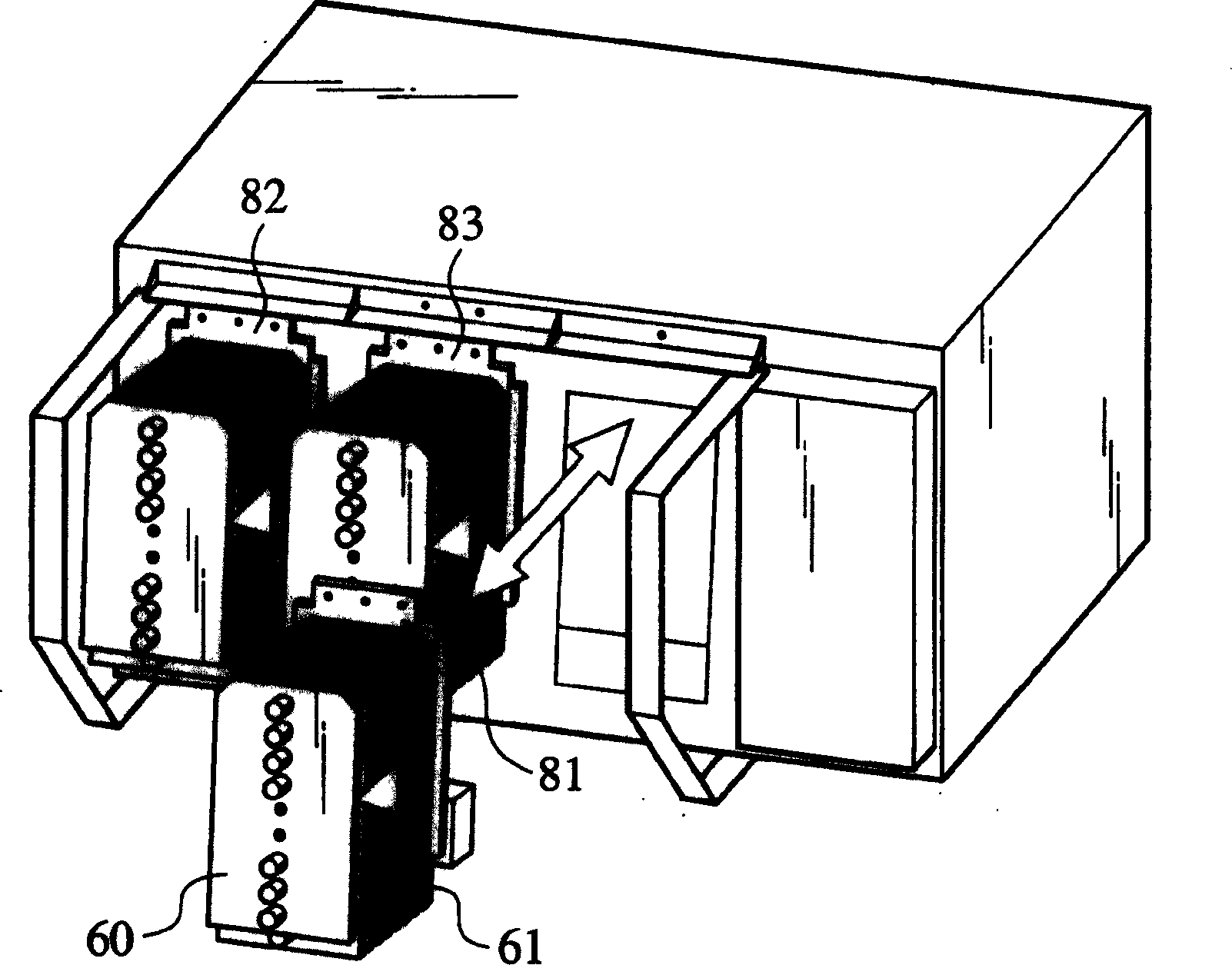
[0031] An electric train control device according to a second embodiment of the present invention will be described in detail with reference to the drawings. image 3 It is a perspective view of the constant-voltage constant-frequency inverter according to the second embodiment of the present invention. Figure 4 It is a perspective view of the cooler of the constant-voltage constant-frequency inverter according to the second embodiment of the present invention. Figure 5 It is a front view of the cooler of the constant-voltage constant-frequency inverter based on the electric vehicle control device according to the second embodiment of the present invention. Figure 6 It is a left side view of the cooler of the constant-voltage constant-frequency inverter based on the electric vehicle control device according to the second embodiment of the present invention. Figure 7 It is a circuit configuration diagram of a constant-voltage constant-frequency inverter based on the electr...
no. 3 Embodiment approach
[0037] An electric train control device according to a third embodiment of the present invention will be described in detail with reference to the drawings. Figure 8 It is a configuration diagram of a variable-voltage variable-frequency inverter according to a third embodiment of the present invention. Figure 9 It is a block diagram of a dynamic braking circuit breaker based on a variable voltage variable frequency inverter according to a third embodiment of the present invention. In addition to Figure 10 Components that are structurally the same as those described in , are assigned the same symbols and descriptions thereof are omitted.
[0038] The variable-voltage variable-frequency inverter system 2 of the electric train control device according to the third embodiment of the present invention has an inverter circuit 25 and an inverter circuit 26 for controlling the AC motor 31 and the AC motor 32, and a dynamic braking system. A circuit breaker circuit 41 and a circuit...
PUM
 Abstract
Description
Claims
Application Information