Weft selection apparatus for a weaving machine

A technology of looms and traction devices, applied in the directions of looms, textiles, textiles, and papermaking, to achieve the effect of reducing additional loads

Inactive Publication Date: 2011-01-26
STAEUBLI AG
View PDF4 Cites 0 Cited by
  • Summary
  • Abstract
  • Description
  • Claims
  • Application Information

AI Technical Summary

Problems solved by technology

[0008] As mentioned above, this type of weft changing device is only suitable for looms with one weaving shed

Method used


Image

  • Weft selection apparatus for a weaving machine
  • Weft selection apparatus for a weaving machine
  • Weft selection apparatus for a weaving machine

Examples


Embodiment Construction

[0022] The weft changing device according to the invention is illustrated by means of a double shed loom with two weft insertion planes placed one above the other.

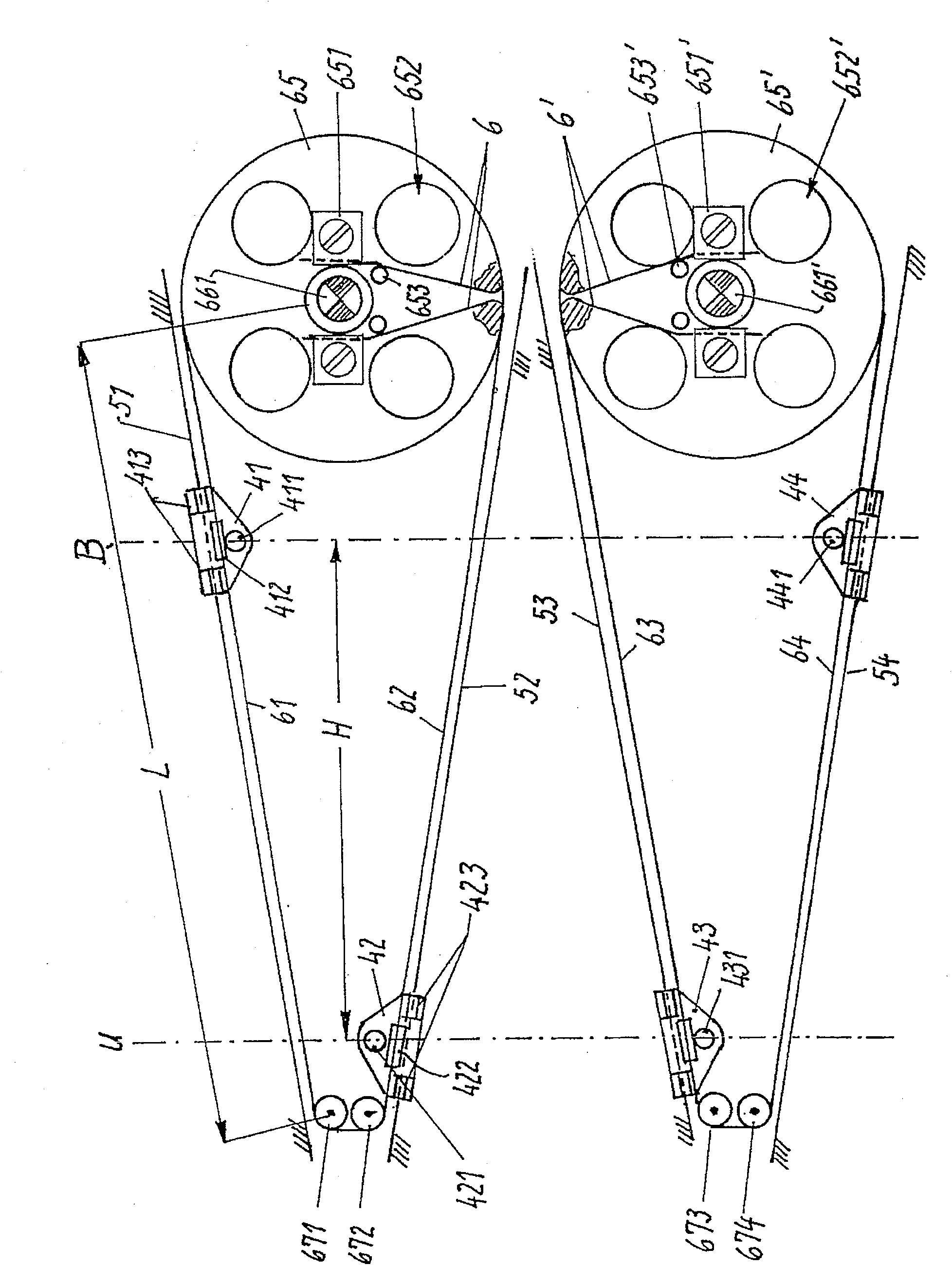
[0023] The coil transfer position U and the standby position B are arranged substantially in a common horizontal plane.

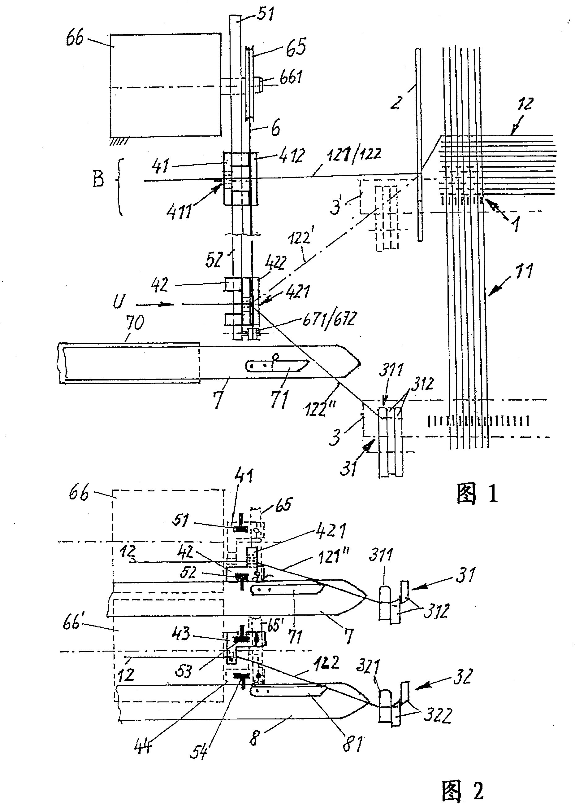
[0024] figure 1 In the right-hand region is indicated the supply of warp threads 11 which, together with the weft threads 12 introduced, produce a base fabric 1 of double-faced fleece after the fabric has been beaten up.

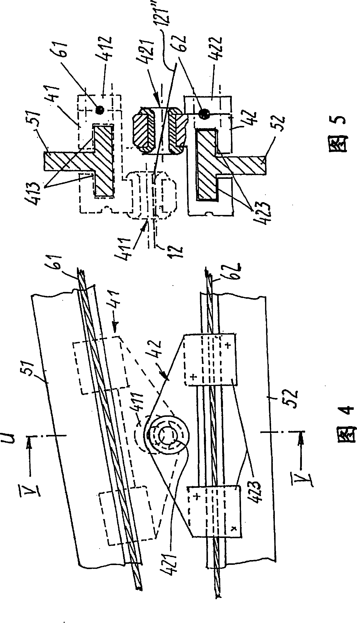
[0025] During the stage of weft insertion by means of the clamping bar 7 with a tucking clamp 71, the sley 3 with the weaving reed is in its final position. A controllable clamping and cutting device 31, 32 for the weft thread 12 is arranged on the sley 3 laterally outside the weaving reed. The clamps 311, 321 and the blades of the scissors 312, 322 are driven in a manner known per se. The driving structure is not shown.

[0026] Laterally on the outside of the base fabri...


PUM


Abstract

The invention relates to a latitude exchanging device for a loom, and each weft insertion element has at least a pair of guide eyes. By the reliability of the confirmation of the weft insertion under the circumstance of even high operating speed, a pair of guide eyes (411, 412; 413, 414) are arranged on the sliding blocks (41, 42) which can mutually move between the standby position (B) and the delivering position (U). The sliding blocks (41, 42) are guiding between the standby position (B) and the delivering position (U) of the guide rails (51, 52) fixed in relation to the support. The sliding blocks (41, 42) of a pair of guide eyes (411, 412) move in a matching shape by the controllable driving device (stepping motor 66, 66'), and a flexible draw gear (6, 6') is guided by a driving wheel (65) and at least a deflecting roll (671, 672), wherein strands (61, 62) moving correspondingly are formed, and the strands (61, 62) are guided in parallel with the guide rails (51, 52) and sliding blocks (41, 42) are fixed on the strands.

Description

technical field [0001] The invention relates to a weft changing device for a weaving machine, wherein each weft insertion element has at least one pair of eyelets (of a yarn feeder), said eyelets being actuatable in a controlled manner. Background technique [0002] A weft changing device of this type is described in EP0293558A1. The substantially vertically oriented guide needles (of the yarn guide) are rigidly suspended from the free end of a rod that oscillates along a horizontal axis. They are oriented tangentially towards the lever arm and carry the eyelets which are located at the front and at the bottom in the direction of movement. The lever is mechanically driven by controllable jaws, oscillating knives and springs. [0003] This arrangement is sufficient for looms with a single weft insertion element. On looms with several superimposed weft insertion planes, the pivot axis of the lever must be oriented vertically. The variable yarn tension and the superposition...

Claims


Application Information

Patent Timeline
Patent Type & Authority Patents(China)
IPC IPC(8): D03D47/38
CPCD03D47/38
Inventor M・布尔克特D・皮聪卡
Owner STAEUBLI AG
Why Eureka
Try Eureka