

Method for placing vacuum glass supporter
A vacuum glass and support technology, which is applied in the field of vacuum glass support placement, can solve problems such as warping and deformation, affecting the appearance, inconsistent displacement direction and size, etc.
Inactive Publication Date: 2016-02-10
黄家军
View PDF4 Cites 0 Cited by
- Summary
- Abstract
- Description
- Claims
- Application Information
AI Technical Summary
Problems solved by technology
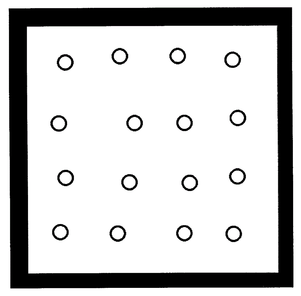
The support fixed with organic sealant, the sealant is heated and melted, the upper and lower glass plates are compressed in the middle under the action of external force, and the glass plate will warp and deform under the action of external force, which will generate a lateral thrust on the support , causing the support to move. Although the movement is only 1-2 mm, it has no effect on the heat insulation and sound insulation effect of the vacuum glass, but this movement affects the appearance, such as figure 1 As shown, when the upper row of supports is initially placed, the supports are on a straight line. After compression, the displacement directions and sizes of each support are inconsistent, and the upper row of supports is not on a straight line. This affects beautiful
Method used
View moreImage
Smart ImageViewing Examples

Examples
Embodiment Construction
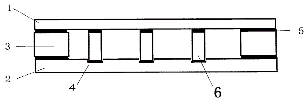
[0010] like figure 2 As shown, before placing the support, open a 1 mm deep groove 4 on the lower glass plate 2 at the position where the support will be placed, then put the support into the groove, then place the auxiliary sealing strip 3 and seal Glue 5, and then cover the upper glass plate 1. Then put the vacuum glass original plate into the vacuum heating furnace for heating and sealing.
Login to View More PUM
 Abstract
The invention aims at providing a method for placing a vacuum glass supporter. The method is used for preventing the supporter from lateral movement. The method for placing the vacuum glass supporter is characterized by comprising the steps of firstly, forming a groove, which is slightly greater than the outside diameter of the supporter, in the surface of a glass sheet where the supporter is required to be placed, and then, placing the supporter in the groove.
Description
technical field [0001] The invention relates to the field of vacuum glass manufacturing, in particular to a method for arranging vacuum glass supports. Background technique [0002] Supports are used in the vacuum glass manufacturing process. The support fixed with organic sealant, the sealant is heated and melted, the upper and lower glass plates are compressed in the middle under the action of external force, and the glass plate will warp and deform under the action of external force, which will generate a lateral thrust on the support , causing the support to move. Although the movement is only 1-2 mm, it has no effect on the heat insulation and sound insulation effect of the vacuum glass, but this movement affects the appearance, such as figure 1 As shown, when the upper row of supports is initially placed, the supports are on a straight line. After compression, the displacement directions and sizes of each support are inconsistent, and the upper row of supports is not ...
Claims
Login to View More Application Information
Patent Timeline
 Patent Type & AuthorityApplications(China)
IPC IPC(8): C03C27/06
Inventor黄家军
Owner黄家军